
Colpitts and Hartley Oscillator: RF Circuit Design Basics
If you’ve ever wondered how radio transmitters, signal generators, or clock circuits produce a steady sine wave, the answer almost always involves an oscillator. For anyone diving into RF circuit design, understanding Colpitts oscillator design and the Hartley oscillator is an essential first step. These two LC feedback oscillators are the backbone of RF electronics and appear in everything from AM radio receivers to VFO (variable frequency oscillator) circuits used by amateur radio operators across India. In this guide, we’ll break down both topologies, derive the frequency equations, discuss practical component selection, and help you build your first oscillator on a breadboard.
What Is an LC Oscillator?
An LC oscillator is a circuit that generates a continuous sinusoidal waveform using an inductor (L) and a capacitor (C) as its frequency-determining elements. The LC pair forms what is called a tank circuit — energy sloshes back and forth between the magnetic field of the inductor and the electric field of the capacitor, creating oscillation at a natural resonant frequency.
Without active amplification, the oscillation would die out due to resistive losses. The active element — usually a BJT transistor or a FET — compensates for these losses by feeding a portion of the output signal back to the input in phase (positive feedback). When the loop gain equals exactly 1 and the phase shift around the loop is 0° (or 360°), sustained oscillation occurs. This condition is described by the Barkhausen stability criterion.
Both the Colpitts and Hartley oscillators satisfy Barkhausen’s criterion but differ in how they implement the feedback network:
- Colpitts: Feedback taken from a capacitive voltage divider
- Hartley: Feedback taken from a tapped inductor (or two inductors)
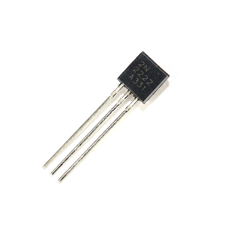
2N2222 NPN Transistor (Pack of 20)
The 2N2222 is a classic NPN transistor widely used in Colpitts and Hartley oscillator circuits. Its high transition frequency (fT up to 300 MHz) makes it ideal for RF oscillators up to 30 MHz.
Colpitts Oscillator Design Explained
The Colpitts oscillator, invented by Edwin Colpitts in 1918, uses a pair of capacitors (C1 and C2) in series as the feedback network, with an inductor (L) completing the tank circuit. Here’s how it works step by step:
Circuit Topology
In the most common BJT version, the transistor is connected in common-emitter (or common-base) configuration. The tank circuit consisting of L, C1, and C2 sits between collector and emitter. The feedback voltage is developed across C2 (the capacitor on the emitter side) and fed back to the base, maintaining oscillation.
Key nodes:
- C1 connects between the collector (output) and the junction of L and C2
- C2 connects between the junction and ground/emitter
- L connects in parallel with the series combination of C1 and C2
- The feedback ratio β = C1 / C2 (must be ≤ 1/A_v to avoid overdrive)
Why Colpitts Is Preferred for RF
The capacitive divider makes the Colpitts topology excellent at high frequencies because:
- Capacitors have lower parasitic inductance than tapped coils
- The ratio C1/C2 is easy to control precisely using fixed or trimmer capacitors
- It produces a purer sine wave compared to relaxation oscillators
- Widely used in VCOs (voltage-controlled oscillators) in PLL circuits
Design Steps for a Colpitts Oscillator
- Choose your target frequency (f): Example — 1 MHz for a medium-wave transmitter
- Select the inductor L: Typically 10 µH to 100 µH for 1–10 MHz range. Use a ferrite-core toroid for better Q factor.
- Calculate the series capacitance: C_series = 1 / (4π²f²L). For f=1 MHz, L=25.3 µH → C_series ≈ 1000 pF
- Split into C1 and C2: Typical ratio C1:C2 = 1:2. So C1 = 3000 pF, C2 = 1500 pF (series combination = 1000 pF)
- Bias the transistor: Use voltage-divider bias (see our BJT biasing guide) for stability
- Add a bypass capacitor at the emitter resistor to maintain AC gain

0.1µF Ceramic Capacitor (Pack of 50)
Ceramic capacitors are the go-to choice for oscillator tank circuits and bypass applications. Low ESR and tight tolerance make these 104 ceramics perfect for RF work and decoupling power rails in oscillator builds.
Hartley Oscillator Circuit
The Hartley oscillator, invented by Ralph Hartley in 1915, uses a tapped inductor (or two inductors in series) to form the feedback network, with a single capacitor completing the tank circuit. It is the conceptual dual of the Colpitts — where Colpitts splits capacitance, Hartley splits inductance.
Circuit Topology
The inductor is centre-tapped or split into L1 and L2. In a common-emitter BJT implementation:
- L1 connects between the collector and the tap point
- L2 connects between the tap point and ground/emitter
- Capacitor C connects across the full inductor (collector to ground)
- Feedback is taken from across L2 back to the base
- Feedback ratio β = L2 / (L1 + L2)
Hartley vs. Colpitts: Key Differences
| Feature | Colpitts | Hartley |
|---|---|---|
| Feedback element | Capacitor divider (C1, C2) | Tapped inductor (L1, L2) |
| Frequency tuning | Vary inductor or cap values | Single variable capacitor |
| RF performance | Better at very high frequencies | Good up to ~30 MHz |
| Construction complexity | Simpler (standard caps) | Needs tapped coil winding |
| Harmonic content | Lower (purer sine) | Slightly higher |
The Hartley oscillator shines in applications where you want to tune the output frequency smoothly using a single variable capacitor (varicap or air-variable cap). Classic AM radio VFOs often use the Hartley topology for exactly this reason.
Frequency Calculation for Both Topologies
Both oscillators produce a frequency governed by the basic LC resonance formula, with a slight adjustment for the feedback elements.
Colpitts Oscillator Frequency
The resonant frequency is determined by L and the series combination of C1 and C2:
C_total = (C1 × C2) / (C1 + C2)
f = 1 / (2π × √(L × C_total))
Example: L = 10 µH, C1 = 1000 pF, C2 = 1000 pF
C_total = 500 pF = 500 × 10⁻¹² F
f = 1 / (2π × √(10 × 10⁻⁶ × 500 × 10⁻¹²))
f = 1 / (2π × √(5 × 10⁻¹⁵))
f ≈ 2.25 MHz
Hartley Oscillator Frequency
The total inductance is L_total = L1 + L2 (assuming no mutual coupling):
L_total = L1 + L2 (+ 2M if coils are wound on same core)
f = 1 / (2π × √(L_total × C))
Example: L1 = 5 µH, L2 = 5 µH, C = 500 pF
L_total = 10 µH
f ≈ 2.25 MHz (same as above — demonstrates duality)
Practical Component Selection
Choosing the right components separates a stable oscillator from one that drifts or won’t start. Here’s what to look for:
Inductors
- Q factor: Higher Q = lower losses = easier to oscillate. Aim for Q > 50 at your target frequency.
- Core material: Air-core for frequencies above 5 MHz; ferrite cores for lower frequencies
- Self-resonant frequency (SRF): Must be at least 3× your operating frequency
Capacitors
- NP0/C0G ceramic capacitors for the tank — extremely stable over temperature
- Avoid electrolytic capacitors in the tank (high ESR, poor frequency performance)
- Use standard ceramic (X7R or similar) for bypass and coupling capacitors
Transistors
- 2N2222A or BC547 for frequencies below 10 MHz
- Ensure fT (transition frequency) is at least 10× your oscillation frequency
- Keep the operating collector current low (1–5 mA) to minimize phase noise
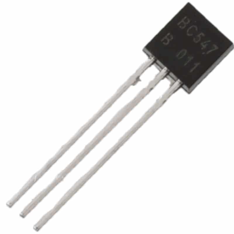
BC547 NPN 100mA Transistor TO-92 (Pack of 10)
The BC547 is a workhorse NPN transistor perfect for low-frequency Colpitts and Hartley oscillators (up to ~5 MHz). Its TO-92 package fits directly into a breadboard for easy prototyping.
Building Your Oscillator on a Breadboard
Ready to get hands-on? Here’s a step-by-step guide to building a 1 MHz Colpitts oscillator on a solderless breadboard using commonly available components in India.
Parts List
- 1× 2N2222 or BC547 NPN transistor
- 1× 25 µH inductor (or wind 30 turns of 0.3 mm enamelled copper wire on a ferrite rod)
- 2× 1 nF (1000 pF) NP0/C0G ceramic capacitors (C1 and C2)
- 1× 0.1 µF ceramic capacitor (supply bypass)
- Resistors: 10kΩ and 2.2kΩ (voltage divider base bias), 470Ω emitter resistor, 4.7kΩ collector resistor
- 9V battery or 9V DC power supply
- Breadboard and jumper wires
Build Steps
- Place the transistor in the middle of the breadboard with leads spread across columns
- Connect the 10kΩ and 2.2kΩ voltage divider between VCC and GND, junction to the base
- Add a 10 µF bypass capacitor from base-divider junction to GND (AC bypass)
- Connect C1 from collector to the L-C junction node
- Connect C2 from the L-C junction node to GND
- Connect L from the collector to GND (across the series C1-C2 combination)
- Add 0.1 µF bypass cap from VCC to GND near the transistor
- Connect output (probe or subsequent stage) from the collector via a 10 nF coupling capacitor
Hook up an oscilloscope probe (or a simple LED-and-resistor indicator) to the collector. Apply 9V and you should see a clean sine wave at approximately 1 MHz.
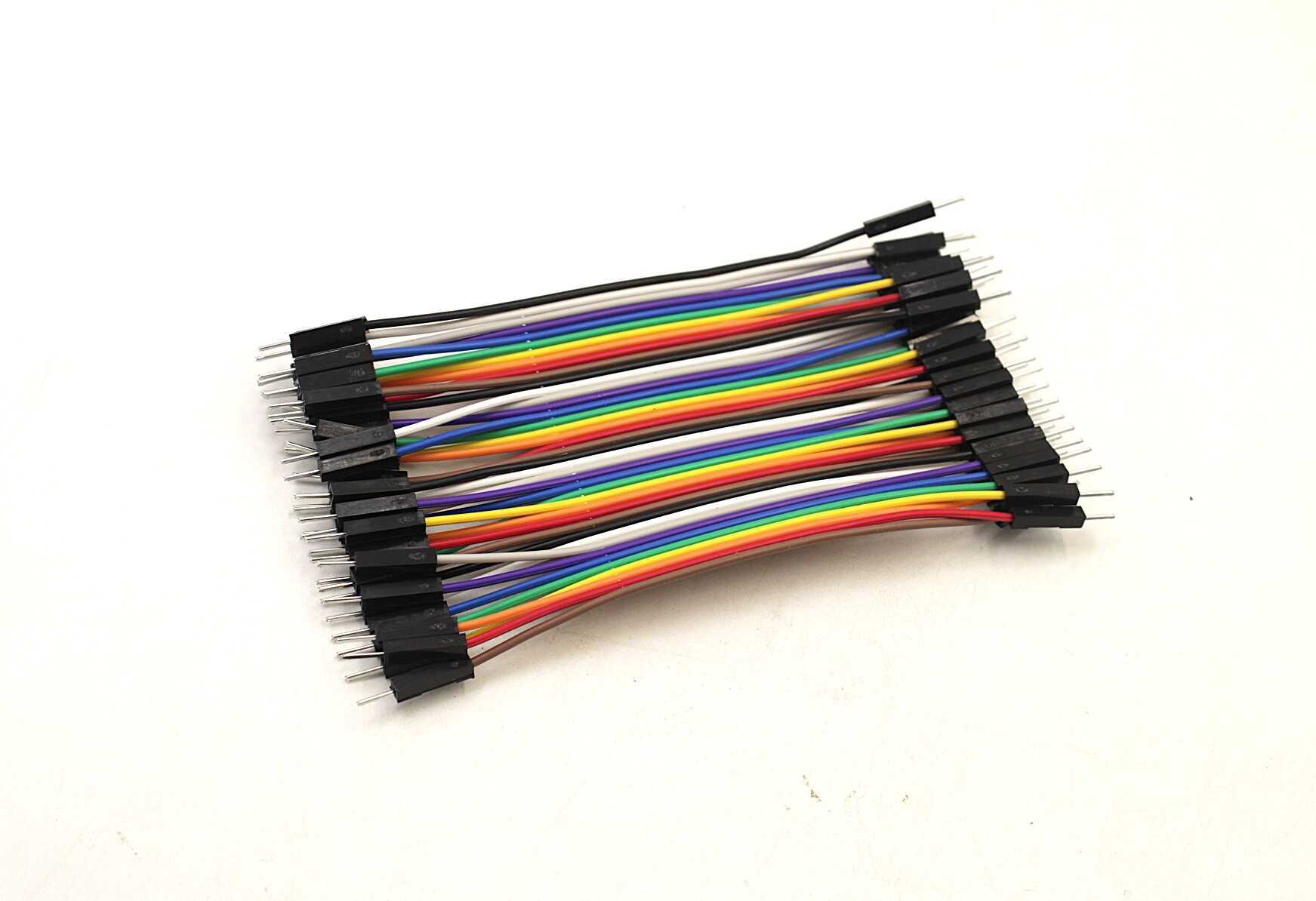
10CM Male To Male Breadboard Jumper Wires 2.54MM – 40Pcs
Essential for breadboard oscillator builds. These 10cm M-M jumper wires fit perfectly for short connections between components, keeping your RF circuit neat and minimising stray inductance pickup.
Real-World Applications in India
Understanding Colpitts and Hartley oscillators opens doors to a variety of exciting projects:
- Amateur (Ham) Radio VFOs: Many Indian ham radio operators (licensed under WPC, Ministry of Communications) build their own CW transmitters using Hartley oscillators tuned to the 40m or 80m bands.
- RF Signal Generators: A bench signal generator for testing FM/AM receivers can be built around a Colpitts oscillator with a varicap diode for electronic tuning.
- Metal Detectors: Beat-frequency oscillator (BFO) metal detectors use two Colpitts oscillators — one reference and one search coil. When metal disturbs the search coil’s inductance, the beat frequency changes audibly.
- RFID Reader Front-Ends: The carrier oscillator in 125 kHz RFID readers is a low-frequency Colpitts circuit driving the transmit coil.
- Clock Circuits: Crystal oscillators are essentially a Colpitts topology where the quartz crystal replaces the inductor, providing exceptional frequency stability for microcontroller clocks.

LCR-T4 LCD Graphical Transistor Tester
Verify your capacitors, inductors, and transistors before building your oscillator. The LCR-T4 measures L, C, R, ESR and even identifies transistor type and pinout — an essential tool for any RF circuit builder.
Frequently Asked Questions
What is the main difference between a Colpitts and a Hartley oscillator?
The Colpitts oscillator uses a capacitive voltage divider (two capacitors C1 and C2) to provide feedback, while the Hartley oscillator uses a tapped inductor (L1 and L2) for feedback. Both use an LC tank circuit to set the oscillation frequency, but the Colpitts generally has better high-frequency performance and lower harmonic distortion.
Why does my Colpitts oscillator not start oscillating?
The most common causes are: (1) insufficient loop gain — increase the C1/C2 ratio or increase transistor biasing current slightly; (2) low Q inductor causing excessive losses — try a different core material or more turns; (3) incorrect biasing — ensure the transistor is in the active region, not saturated or cut off; (4) stray capacitance from breadboard wiring shifting the resonant frequency.
How do I tune the frequency of a Colpitts oscillator design?
You can change the oscillation frequency by replacing the inductor with one of a different value, changing both capacitors while maintaining the C1/C2 ratio, or adding a variable capacitor (trimmer or air-variable) in parallel with the inductor. For electronic tuning (VCO), replace the tuning capacitor with a varicap diode (e.g., BB105) and control its capacitance with a DC voltage.
Can I use a MOSFET instead of a BJT in a Hartley oscillator?
Yes. JFETs (like the J310 or BF245) and MOSFETs are commonly used in Hartley and Colpitts oscillators for their high input impedance, which loads the tank circuit less and improves frequency stability. The design approach is similar; just replace the BJT bias network with gate-bias resistors appropriate for the FET type.
What is the Barkhausen criterion and why does it matter for oscillators?
The Barkhausen stability criterion states that for sustained oscillation in a feedback amplifier, the loop gain must equal 1 (|Aβ| = 1) and the total phase shift around the loop must be 0° or 360°. If the loop gain is less than 1, oscillations die out. If it is greater than 1, the output clips and becomes distorted. Both Colpitts and Hartley oscillators are designed so that the transistor provides exactly enough gain to compensate for tank circuit losses.
Ready to Build Your First Oscillator?
Get all the components you need — transistors, capacitors, resistors, and breadboard wires — from Zbotic. We stock a wide range of electronics components perfect for RF circuit design projects across India.


Add comment