
Temperature sensing is at the heart of countless electronics projects — from smart home thermostats and battery management systems to 3D printer hotends and industrial process control. Among the many sensor options available, thermistors stand out for their excellent sensitivity, low cost, and compact size. But when you start shopping, you immediately encounter two variants: NTC (Negative Temperature Coefficient) and PTC (Positive Temperature Coefficient).
Which one should you choose? How do they differ electrically? And how do you actually wire them into a working circuit? This comprehensive guide answers all of those questions with practical circuit examples, component selection tips, and real Arduino code.
1. What Is a Thermistor?
A thermistor (a portmanteau of thermal + resistor) is a type of resistor whose resistance changes significantly and predictably with temperature. Unlike standard resistors that are designed to maintain a constant value regardless of heat, thermistors are engineered to exploit this property as a feature.
Thermistors are typically made from metal oxide semiconductors — manganese, nickel, cobalt, copper, and iron oxides sintered together and encapsulated in epoxy, glass, or a stainless steel probe. The manufacturing process determines whether the component exhibits NTC or PTC behaviour.
Key advantages of thermistors over other temperature sensors:
- High sensitivity: Resistance changes 3–5% per °C — far more than a platinum RTD (0.4%/°C)
- Low cost: A typical 10kΩ NTC costs ₹5–15 in India
- Fast response time: Small bead types respond in under 1 second
- No external reference needed: Works directly with a voltage divider and ADC
- Wide range: Available for –55°C to +300°C depending on type
The main limitation is non-linearity. Unlike linear sensors such as the LM35, a thermistor’s resistance-to-temperature curve is exponential, requiring mathematical conversion (the Steinhart-Hart equation) for accurate readings.

LM35 Temperature Sensor
A linear analog temperature sensor — great comparison point to understand why thermistors are preferred for high-sensitivity applications.
2. NTC Thermistors: Resistance Drops with Heat
An NTC thermistor has a negative temperature coefficient, meaning its resistance decreases as temperature increases. This is the more common type and the one most hobbyists encounter in temperature monitoring projects.
How NTC Works Physically
NTC thermistors are made from semiconductor materials. At low temperatures, charge carriers (electrons and holes) are bound in the crystal lattice and cannot move freely, resulting in high resistance. As temperature rises, thermal energy liberates more charge carriers, dramatically increasing conductivity and reducing resistance.
The relationship follows an exponential law:
R(T) = R₀ × e^(B × (1/T - 1/T₀))
Where:
- R(T) = resistance at temperature T (in Kelvin)
- R₀ = reference resistance (typically at 25°C = 298.15K)
- B = material constant (typically 3000–5000K for NTC)
- T₀ = reference temperature (298.15K)
Typical NTC Characteristics
| Temperature (°C) | Resistance (10kΩ NTC, B=3950) |
|---|---|
| 0°C | ~32,650 Ω |
| 25°C | 10,000 Ω (nominal) |
| 50°C | ~3,602 Ω |
| 100°C | ~675 Ω |
Common NTC Applications
- 3D printer hotend and heated bed temperature control
- Battery pack thermal management in EVs and power banks
- Air conditioning and refrigeration thermostats
- Medical devices (oral thermometers, incubators)
- Inrush current limiting in power supplies
3. PTC Thermistors: Resistance Rises with Heat
A PTC thermistor has a positive temperature coefficient — its resistance increases as temperature rises. The behaviour, however, depends on the specific type of PTC.
Silistor (Linear) PTC
Silistors are made from silicon and exhibit a gradual, nearly linear increase in resistance with temperature (about +0.7%/°C). They are used as temperature sensors in power transistors, motor windings, and transformer coil protection where the sensor must be embedded in the winding itself.
Switching (Barium Titanate) PTC
The more dramatic variety uses barium titanate ceramics doped with rare-earth elements. Below a critical Curie temperature (typically 60°C–120°C depending on formulation), resistance is low (tens of ohms). Once the Curie temperature is exceeded, resistance jumps by several orders of magnitude — sometimes from 100Ω to 10MΩ within just 20°C.
This switching behaviour makes barium titanate PTCs ideal for:
- Resettable fuses (polyfuses): Current overload heats the PTC → resistance spikes → current drops → device protected → PTC cools → resistance drops again (self-healing)
- Self-regulating heaters: The PTC limits its own current as it heats up, creating a constant-temperature heating element
- Motor starter circuits: Limit inrush current until motor reaches operating speed
- Degaussing coils: In old CRT monitors, a PTC gradually reduced degaussing current
4. NTC vs PTC: Side-by-Side Comparison
| Property | NTC Thermistor | PTC Thermistor |
|---|---|---|
| Resistance vs Temp | Decreases (negative) | Increases (positive) |
| Curve shape | Smooth exponential | Sharp switching (ceramic) or linear (silistor) |
| Primary use | Temperature measurement | Overcurrent protection, self-regulating heat |
| Sensitivity | 3–5%/°C | Variable; very high near Curie point |
| Operating range | –55°C to +300°C | –40°C to +125°C (silistor); varies (ceramic) |
| Self-healing | No | Yes (polyfuse type) |
| ADC reading | Good linearity after math conversion | Not ideal for ADC (switching type) |
| Common package | Bead, disc, epoxy-coated | Disc, SMD, radial leaded |
Rule of thumb: If you need to measure temperature accurately with a microcontroller, use an NTC. If you need to protect a circuit from overtemperature or overcurrent, use a PTC polyfuse.
5. Building the Classic Voltage Divider Circuit
The most common way to read an NTC thermistor with a microcontroller is through a resistor voltage divider. The output voltage changes as the thermistor resistance changes, and an ADC converts this to a digital reading.
Circuit Diagram
3.3V or 5V
   |
  [R_fixed] ← fixed resistor (usually 10kΩ)
   |
   +-----> A0 (ADC pin)
   |
  [NTC]   ← thermistor
   |
  GND
Choosing the Fixed Resistor Value
For maximum sensitivity, the fixed resistor should equal the thermistor’s nominal resistance at the midpoint of your measurement range. For a 10kΩ NTC measuring 0°C–50°C, a 10kΩ fixed resistor is ideal — the output swings from about 0.76V (at 0°C) to 2.08V (at 50°C) on a 3.3V supply.
Wiring to Arduino
- Connect 5V → fixed resistor (10kΩ) → junction → thermistor → GND
- Connect junction to Arduino A0
- No additional components needed for a basic reading
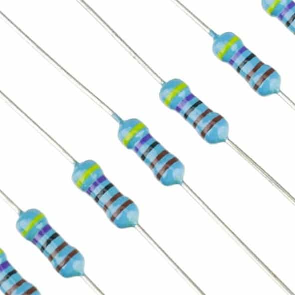
1/4W Metal Film Resistors (Pack of 100)
Use a 10kΩ metal film resistor as the fixed resistor in your NTC voltage divider for accurate, low-drift readings.
6. Reading Temperature with Arduino
Here is a complete Arduino sketch to read temperature from a 10kΩ NTC (B = 3950) using the Steinhart-Hart simplification:
// NTC Thermistor Temperature Reading
// Thermistor: 10kΩ NTC, B = 3950
// Fixed resistor: 10kΩ connected to VCC

const int THERMISTOR_PIN = A0;
const float VCC = 5.0;           // Supply voltage
const float R_FIXED = 10000.0;  // Fixed resistor (10kΩ)
const float R_NOMINAL = 10000.0; // NTC nominal at 25°C
const float T_NOMINAL = 25.0;    // Nominal temp in °C
const float B_COEFFICIENT = 3950.0; // Beta value

void setup() {
  Serial.begin(9600);
}

void loop() {
  int raw = analogRead(THERMISTOR_PIN);
  float voltage = (raw / 1023.0) * VCC;

  // Calculate NTC resistance
  float resistance = R_FIXED * (VCC / voltage - 1.0);

  // Steinhart-Hart simplified equation
  float steinhart = resistance / R_NOMINAL;
  steinhart = log(steinhart);
  steinhart /= B_COEFFICIENT;
  steinhart += 1.0 / (T_NOMINAL + 273.15);
  float tempC = (1.0 / steinhart) - 273.15;

  Serial.print("Temperature: ");
  Serial.print(tempC, 2);
  Serial.println(" °C");

  delay(1000);
}
Understanding the Output
Upload this sketch, open the Serial Monitor at 9600 baud, and you will see temperature readings update every second. Typical accuracy is ±1°C across 0–50°C without individual calibration.
7. Steinhart-Hart Equation Explained
The Steinhart-Hart equation is the standard mathematical model for converting NTC thermistor resistance to temperature:
1/T = A + B·ln(R) + C·(ln(R))³
Where T is in Kelvin and A, B, C are material constants obtained from the datasheet or by calibrating against three known temperatures.
For most hobbyist work, the simplified two-parameter form (dropping the C term and using the Beta coefficient) is accurate to ±0.5°C over a 50°C range. This is what the Arduino sketch above uses.
For high-precision applications (±0.1°C), use all three Steinhart-Hart coefficients from the datasheet and solve the full equation.
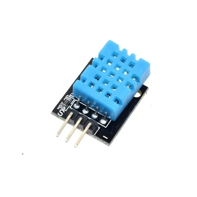
DHT11 Digital Temperature & Humidity Sensor
Want a digital alternative to NTC? The DHT11 outputs calibrated temperature and humidity data directly over a single wire with no math needed.
8. PTC as a Resettable Fuse (Polyfuse)
One of the most practical uses of PTC thermistors in modern electronics is as polyfuses — self-resetting overcurrent protection devices. Unlike a glass fuse that physically blows and must be replaced, a polyfuse trips under overcurrent, then resets automatically when cooled.
How a Polyfuse Works
- Under normal current, the polyfuse remains cool and presents low resistance (typically 0.1–1Ω)
- If current exceeds the trip rating, resistive heating raises the PTC above its Curie point
- Resistance jumps to thousands of ohms — the current drops to a safe hold level
- When the fault is removed and the PTC cools, resistance returns to normal
Typical Specifications to Look For
- I_hold: Maximum continuous current without tripping
- I_trip: Current that will definitely trip the device (usually 2× I_hold)
- V_max: Maximum voltage across the PTC
- R_initial: Resistance at 23°C before any trip events
9. Choosing the Right Thermistor for Your Project
Use this decision tree to select the right sensor:
Choose an NTC if you need to:
- Measure temperature continuously over a wide range
- Interface directly with a microcontroller ADC
- Monitor battery or motor temperature
- Build a thermostat or temperature logger
- Protect a circuit from overheating by reading temperature and cutting power in software
Choose a PTC (polyfuse) if you need to:
- Protect a circuit from sustained overcurrent without replacing a fuse
- Create a self-regulating heater element
- Add resettable protection to USB ports, Li-Ion cells, or speaker outputs
NTC Key Parameters to Match
| Parameter | Typical Value | Effect |
|---|---|---|
| Nominal resistance (R25) | 1kΩ, 10kΩ, 100kΩ | Sets mid-scale; match to fixed resistor |
| Beta (B) value | 3000–5000K | Higher B = more sensitive but more non-linear |
| Tolerance | ±1%, ±5% | Lower = more accurate without calibration |
| Dissipation constant | 1–10 mW/°C | Self-heating error budget |

10CM Male to Female Breadboard Jumper Wires – 40Pcs
Connect your NTC thermistor to the Arduino breadboard cleanly with these 40-piece M-F jumper wire packs.
10. Common Mistakes and How to Avoid Them
Mistake 1: Self-Heating Error
Passing too much current through an NTC heats it up, causing a reading that is higher than the actual ambient temperature. Keep excitation current below 100µA for high-accuracy applications. With a 10kΩ NTC on 5V, the divider passes 5V/20kΩ = 250µA — acceptable for most applications, but not precision thermometry.
Mistake 2: Wrong Beta Value in Code
Using a generic B=3950 when your specific thermistor has B=3977 will cause systematic error across the range. Always check your datasheet. If you don’t have one, calibrate against two known temperatures to calculate B empirically.
Mistake 3: Using a PTC Where an NTC Is Needed
A switching PTC will not give useful ADC readings across a temperature range — it essentially acts as an open circuit above its Curie temperature. Always use NTC for analog temperature measurement.
Mistake 4: Ignoring the ADC Reference Voltage
If you are using Arduino with a 3.3V supply (e.g., 3.3V Pro Mini), update the VCC constant in your code accordingly. Using 5.0 with a 3.3V supply causes systematic errors in the resistance calculation.
Mistake 5: Placing the Thermistor in the Wrong Position
If you put the NTC below the fixed resistor (between the junction and GND), the voltage divider formula inverts — Vout rises with temperature instead of falling. Either topology works as long as your math matches your wiring.

LCR-T4 Component Tester (Transistor, Capacitor, Resistor)
Verify the actual resistance of your NTC thermistor at room temperature before wiring it up. This affordable tester reads R, C, and more.
Frequently Asked Questions
Can I use an NTC thermistor with a 3.3V Arduino (like the Pro Mini)?
Yes. Simply set VCC = 3.3 in your sketch. The voltage divider works identically; only the scale changes. Ensure analogReference() matches your supply.
What is the difference between a thermistor and a PT100/PT1000?
PT100/PT1000 are Platinum RTDs — they are far more linear (0.4%/°C), accurate to ±0.1°C, and stable over –200°C to +850°C. However, they require a precision current source and are 10–100× more expensive. Thermistors win on cost and sensitivity for the 0°C–100°C range.
My thermistor reads room temperature as 50°C. What is wrong?
Most likely your fixed resistor value is wrong, or you have the NTC and fixed resistor positions swapped. Check the voltage at the ADC pin with a multimeter — at 25°C with a 10kΩ NTC and 10kΩ fixed resistor on 5V, you should read approximately 2.5V.
Can I use multiple NTC thermistors on the same Arduino?
Yes. Wire each thermistor to its own voltage divider circuit and connect to separate analog pins (A0, A1, A2, etc.). Read each pin independently in your code.
What is the maximum temperature an NTC thermistor can measure?
Most standard NTC epoxy-coated thermistors are rated to 125°C or 150°C. High-temperature glass-encapsulated bead types can reach 300°C. Check the maximum continuous operating temperature in your datasheet.
Is a thermistor polarity sensitive?
No. Thermistors are passive resistive components with no polarity. You can connect either lead to VCC or GND without damage.
Conclusion
NTC and PTC thermistors are both incredibly useful components, but for entirely different jobs. The NTC thermistor is your go-to for analog temperature measurement — wire it in a voltage divider, read the ADC, apply the Steinhart-Hart equation, and you have accurate temperature data for under ₹15 in parts. The PTC polyfuse takes care of protection automatically, tripping under overcurrent and resetting once the fault clears — no microcontroller required.
For most Arduino and ESP32 projects, a 10kΩ NTC with B=3950 paired with a matching 10kΩ fixed resistor gives you everything you need. Add the code above, verify your wiring, and you will have a working temperature sensor in under 10 minutes.


Add comment