
Monitoring electricity consumption at home or in your workshop is one of the most practical electronics projects you can build. A current transformer (CT) sensor is a non-invasive, safe, and accurate way to measure AC current flowing through a wire — without cutting the wire or interrupting the circuit. Combined with an Arduino and a few passive components, you can build a complete DIY energy monitor that measures voltage, current, power factor, and real power in watts.
This guide walks you through the complete theory of CT sensors, how to size your burden resistor, condition the signal for Arduino’s ADC, and write firmware that accurately calculates RMS current and apparent power. You will also learn how to extend the project to measure true (real) power using a voltage reference.
What Is a Current Transformer CT Sensor?
A current transformer is a type of instrument transformer designed to produce an AC current in its secondary winding proportional to the AC current in its primary winding. Unlike voltage transformers, CT sensors work on current — not voltage. The primary “winding” is often just the wire carrying the load current threaded through the CT core; the secondary winding is wound many times around the same toroidal core.
The most popular CT sensor for DIY energy monitoring is the YHDC SCT-013 series. These split-core clamp-on sensors can be clipped onto an existing wire without any electrical connection to the monitored circuit — making them completely safe to use on live mains wiring when handled correctly.
Common variants include:
- SCT-013-000: 0–100A range, current output (requires external burden resistor)
- SCT-013-030: 0–30A range, voltage output (1V at full scale, internal burden resistor)
- SCT-013-060: 0–60A range, voltage output (1V at full scale)
How CT Sensors Work
The fundamental principle is electromagnetic induction. When AC current flows through the primary conductor (the wire you are monitoring), it creates a changing magnetic field in the ferrite core. The secondary winding of the CT sensor cuts through this changing flux and generates an induced EMF — producing a proportional secondary current.
The turns ratio determines the output current:
I_secondary = I_primary / turns_ratio

Example: SCT-013-000 has 1800:1 turns ratio
At 100A primary: I_secondary = 100/1800 = 55.6mA
This secondary current is very small (milliamps range). To convert it to a voltage the Arduino ADC can read, you connect a burden resistor across the CT output terminals. The CT forces its secondary current through this resistor, developing a proportional AC voltage.
The critical constraint is that a CT sensor must NEVER be operated with its secondary terminals open-circuited. An open-circuit CT will develop a dangerously high voltage across its terminals, potentially destroying the sensor and creating a shock hazard. Always have the burden resistor connected before connecting the primary current.
CT Sensor vs ACS712 Hall Effect Sensor
| Feature | CT Sensor (SCT-013) | ACS712 Hall Effect |
|---|---|---|
| Isolation | Complete galvanic isolation | None (shares GND with Arduino) |
| AC Safety | Safe for mains (with precautions) | Not suitable for direct mains |
| Installation | Non-invasive (clamp-on) | Requires wire break-in |
| DC Measurement | No (AC only) | Yes (AC and DC) |
| Cost | Slightly higher | Lower |
| Accuracy | Higher (<1% at rated current) | Moderate (~1.5%) |
For mains AC monitoring (230V Indian standard), always use a CT sensor with galvanic isolation. The ACS712 is better suited for low-voltage DC applications.
Components Required
- YHDC SCT-013-000 CT sensor (100A, current output)
- Arduino Uno or Nano
- Burden resistor: 33Ω or 68Ω (1/2W, 1% tolerance)
- Two 10kΩ resistors (voltage divider for bias)
- Two 10μF capacitors (electrolytic, 16V or higher)
- 3.5mm audio jack socket (to connect CT sensor plug)
- Breadboard and jumper wires
- Optional: 16×2 LCD with I2C backpack for display
- Optional: ACS712 module for DC baseline comparison
Calculating the Burden Resistor
The burden resistor converts the CT’s secondary current into a voltage. You need to size it so the peak voltage from the CT never exceeds the Arduino ADC’s reference voltage (5V or 3.3V). For best accuracy, aim for the peak output voltage to reach about 80–90% of the ADC range.
For SCT-013-000 (100A max, 1800:1 turns ratio):
Max secondary current (RMS) = 100A / 1800 = 55.6mA
Max secondary current (peak) = 55.6mA × √2 = 78.6mA

Target peak output voltage = 2.5V (half of 5V ADC range)

Burden resistor = 2.5V / 78.6mA = 31.8Ω → Use 33Ω standard value

Verification: At 100A primary
Voltage at ADC input (peak) = 78.6mA × 33Ω = 2.59V ✓
With DC bias of 2.5V, signal swings: 2.5V ± 2.59V → clipped!

Actual safe range: use 33Ω for up to ~80A, or reduce to 22Ω for full 100A
For the bias circuit (detailed in the next section), the signal must stay between 0V and 5V at all times. Since the CT output is AC (swings positive and negative), you add a 2.5V DC bias so the signal swings between 0V and 5V centered at 2.5V.
Signal Conditioning Circuit
The signal conditioning stage has three functions:
- Burden resistor: Converts secondary current to AC voltage.
- DC bias voltage divider: Adds 2.5V DC offset so the AC signal is centered in the ADC range (not negative).
- Decoupling capacitors: Filters the bias reference to reduce noise.
The bias is created by a simple voltage divider from the 5V rail using two 10kΩ resistors. The midpoint (2.5V) connects to one terminal of the burden resistor, and the other terminal connects to the Arduino analog pin. The CT sensor output (3.5mm jack) connects across the burden resistor.
Add a 10μF capacitor from the 2.5V bias point to GND to stabilize the reference. Add another 10μF between the analog input pin and GND to filter high-frequency noise.
Wiring Diagram
| Connection | Details |
|---|---|
| CT Sensor plug → 3.5mm jack socket | Tip = signal, Sleeve = GND |
| Jack Tip — Burden Resistor (33Ω) — Jack Sleeve | Burden resistor across CT output |
| Junction (Tip + R burden) → A0 | Arduino analog input |
| 5V → R1(10kΩ) → bias node → R2(10kΩ) → GND | Voltage divider creates 2.5V bias |
| Bias node → Jack Sleeve | Connects bias to CT output reference |
| 10μF cap: Bias node to GND | Decouples bias reference |
Safety note: Never touch the CT sensor clip or the burden resistor circuit while the CT is clamped on a live wire and the clip is open. Always install the CT clip on the wire first, connect all circuit components, then power on the Arduino.
Arduino Code for RMS Current Measurement
RMS (Root Mean Square) current is what utility meters measure. The code below samples the ADC at high speed over one complete 50Hz cycle (20ms) and computes the RMS value using the mathematical definition.
// CT Sensor AC Current Measurement
// SCT-013-000 with 33 ohm burden resistor
// Signal connected to A0, biased at 2.5V

const int CT_PIN = A0;
const int SAMPLES = 1480;       // Samples per measurement window (~2 cycles at 50Hz)
const float VREF = 5.0;         // Arduino reference voltage
const float ADC_STEPS = 1023.0; // 10-bit ADC
const float BURDEN_R = 33.0;    // Burden resistor in ohms
const float TURNS = 1800.0;     // CT turns ratio
const float CALIBRATION = 1.0;  // Fine-tune after calibration

float measureRMSCurrent() {
  long sumSquares = 0;
  int sample;
  float voltage;

  for (int i = 0; i < SAMPLES; i++) {
    sample = analogRead(CT_PIN);

    // Remove DC bias (2.5V = 512 ADC counts)
    voltage = ((float)sample - 512.0) * (VREF / ADC_STEPS);

    // Convert voltage to secondary current
    float iSecondary = voltage / BURDEN_R;

    // Convert to primary current
    float iPrimary = iSecondary * TURNS;

    sumSquares += (long)(iPrimary * iPrimary * 100); // Scale to avoid float overflow
  }

  // RMS = sqrt(sum of squares / N)
  float rms = sqrt((float)sumSquares / (SAMPLES * 100.0));
  return rms * CALIBRATION;
}

void setup() {
  Serial.begin(9600);
  Serial.println("CT Sensor AC Power Monitor");
  Serial.println("--------------------------");
}

void loop() {
  float irms = measureRMSCurrent();

  // Apparent power assuming Indian 230V standard
  float apparentPower = irms * 230.0; // VA

  Serial.print("Irms: ");
  Serial.print(irms, 2);
  Serial.print(" A  |  Apparent Power: ");
  Serial.print(apparentPower, 0);
  Serial.println(" VA");

  delay(2000);
}
Calculating Real Power and Power Factor
Apparent power (VA) is not the same as real power (Watts). Real power accounts for the phase difference between voltage and current — the power factor. For resistive loads (heaters, incandescent bulbs), power factor ≈ 1.0 and VA ≈ Watts. For inductive loads (motors, transformers), power factor can be 0.6–0.8.
To measure real power, you need to also sample the AC voltage using a second channel with a voltage transformer or voltage divider (for isolated measurement). The real power is calculated as:
Real Power (W) = (1/N) × Σ(V_instantaneous × I_instantaneous)

Power Factor = Real Power (W) / Apparent Power (VA)
The open-source EmonLib library (by OpenEnergyMonitor) implements this calculation efficiently for Arduino. Install it via Library Manager and use emon1.calcVI(20, 2000) for simultaneous voltage and current measurement.
Calibration Procedure
- Connect a known resistive load: Use a 100W incandescent bulb (actual draw ~0.43A at 230V) or a rated electric iron.
- Measure actual current: Use a True-RMS clamp meter for reference.
- Calculate calibration factor:
calibration = reference_Irms / arduino_Irms - Update CALIBRATION constant in the code and re-flash.
- Re-check at different loads (10%, 50%, 100% of rated current) for linearity.
Typical calibration factors for SCT-013-000 with 33Ω burden on a 5V Arduino range from 0.95 to 1.08 depending on component tolerances and ADC reference accuracy.
Recommended Products from Zbotic

20A Range Current Sensor Module ACS712
Perfect complement to CT sensor projects — use the ACS712 to measure DC currents in battery branches while the CT sensor handles AC mains monitoring.
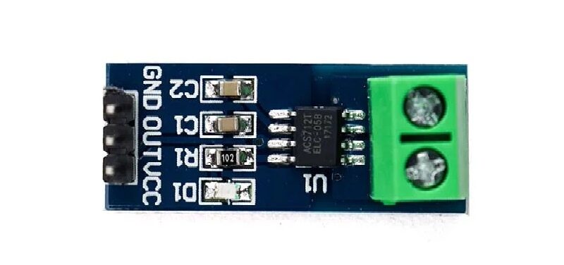
5A Range Current Sensor Module ACS712
For low-power circuits up to 5A — the 185mV/A sensitivity gives excellent resolution when monitoring small appliances and IoT devices.
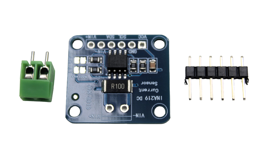
CJMCU-219 INA219 I2C Power Monitoring Module
High-accuracy I2C power monitor — ideal for solar charge monitoring and UPS applications alongside your AC mains CT sensor setup.
Frequently Asked Questions
Q: Is it safe to use a CT sensor on live 230V mains wiring?
The CT sensor itself provides galvanic isolation — your measurement circuit never touches the high-voltage side. However, you must follow electrical safety practices: use a properly rated CT sensor (1000V insulation class), ensure the sensor housing is fully closed when clamped, and never open the CT clip while it is clamped on a live wire with the secondary open-circuited. If you are unsure, have a qualified electrician install the CT sensor on the wire inside your distribution board.
Q: Why does my CT sensor read current even when the appliance is off?
This is a zero-drift issue. The ADC bias might not be exactly 512 counts at zero current. Add a zero-offset calibration: measure the ADC reading with no current flowing and subtract that offset in software. Also check that no other current is flowing on the same phase leg you are monitoring.
Q: Can I use a CT sensor to measure 3-phase power?
Yes, but you need one CT sensor per phase (three total for a 3-phase system). Each CT is connected to a separate Arduino analog pin. Total 3-phase power is the sum of the three phase powers. You also need proper phase voltage references for each phase to calculate real power accurately.
Q: What is the difference between SCT-013-000 and SCT-013-030?
The SCT-013-000 produces a current output (0–50mA at full scale) and requires an external burden resistor — giving you control over the output voltage range. The SCT-013-030 has an internal burden resistor and produces a 0–1V output at its rated current (0–30A). The “000” variant is more flexible for custom ranges; the “030” variant is plug-and-play simpler.
Q: How accurate is DIY CT sensor measurement versus a utility meter?
With proper calibration, a CT sensor + Arduino setup can achieve ±2–3% accuracy for current measurement and ±3–5% for power, limited mainly by ADC resolution (10-bit = 0.1% step, but noise adds up). Commercial utility meters achieve ±0.5–1%. For home monitoring purposes, ±3% is more than sufficient. Using a 12-bit ADC (ADS1115 module) reduces quantization error significantly.
Q: Can the CT sensor handle sudden current spikes (motor starting)?
Yes, but the peak current must not exceed the rated input of the CT (100A for SCT-013-000). Motor starting currents can be 5–8× running current. For a 5A motor, starting current could reach 40A — well within the CT’s range. The Arduino ADC will clip the measurement during the spike, but steady-state readings are unaffected.
Build your own energy monitor with current sensors and modules available at Zbotic. Free shipping on orders above ₹999. All sensors tested and ready to ship across India.


Add comment