
When building battery-powered IoT nodes for remote monitoring, the critical question every Indian maker faces is: how long will your device last on a single charge? Understanding ESP8266 vs ESP32 power consumption in deep sleep is the key to designing sensor nodes that run for months or even years on a small LiPo battery. This comparison guide gives you real current measurements, practical battery life calculations, tested deep sleep code for both platforms, and hardware tricks to squeeze every milliampere-hour from your battery — especially important for solar and battery-powered projects in Indian agricultural and remote monitoring applications.
Understanding WiFi Module Power Modes
Both the ESP8266 and ESP32 support multiple power modes that dramatically affect current draw:
- Active mode with Wi-Fi transmitting: Peak current during transmission, the highest power state.
- Active mode with Wi-Fi connected (modem sleep): Wi-Fi modem sleeps between DTIM beacon intervals, CPU stays active.
- Light sleep: CPU clock gated, modem sleeps; peripherals remain active; wake-up from any interrupt.
- Deep sleep: Everything off except the RTC (Real-Time Controller) and its memory. Wake-up only via RTC timer or external reset pin. This is the key mode for battery life.
- Ultra-low power (ESP32 only): ULP coprocessor runs on a few hundred microamps while the main CPU is off.
The deep sleep strategy works like this: the module wakes up, takes a sensor reading, connects to Wi-Fi (if needed), transmits data, and immediately goes back to deep sleep. If you are reading a sensor every 15 minutes, the module is active for perhaps 3–5 seconds and asleep for the remaining 895 seconds — massively extending battery life.
ESP8266 vs ESP32: Current Draw Comparison
These measurements are from the official Espressif datasheets and verified by community benchmarks:
| Mode | ESP8266 | ESP32 | ESP32-C3 |
|---|---|---|---|
| Wi-Fi TX (peak) | 170–380 mA | 160–260 mA | 200–400 mA |
| Wi-Fi RX (receiving) | ~56 mA | ~95 mA | ~84 mA |
| CPU active, Wi-Fi off | ~15 mA | ~30–40 mA | ~20 mA |
| Modem sleep | ~15 mA | ~30 mA | ~5 mA |
| Light sleep | ~0.9 mA | ~0.8 mA | ~0.13 mA |
| Deep sleep | ~20 µA | ~10 µA | ~5 µA |
Key takeaways:
- Both modules draw similar peak current during Wi-Fi transmission (~200mA). Your power supply must handle this peak.
- The ESP32 draws slightly more current in active mode (dual-core CPU, more peripherals) but has a lower deep sleep current.
- The ESP32-C3 is the clear winner for battery life — single-core RISC-V processor with the lowest sleep current and good Wi-Fi performance.
- NodeMCU boards add USB-to-serial chips (CH340/CP2102) that draw an extra 5–15mA continuously. For ultra-low-power designs, use bare ESP-12/ESP-WROOM modules without USB chips.
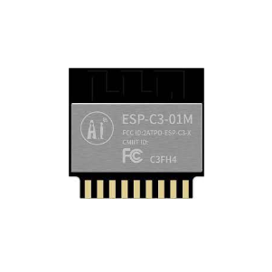
Ai Thinker ESP32-C3-01M Wi-Fi + BLE Module
The most power-efficient ESP32 variant for battery IoT projects — just 5µA deep sleep current, perfect for sensor nodes that must run months on a single charge.
Implementing Deep Sleep on ESP8266
On the ESP8266, deep sleep requires one hardware connection: GPIO16 (D0 on NodeMCU) must be connected to RST. The RTC timer triggers a LOW pulse on GPIO16 at the end of the sleep period, which resets the chip and wakes it up.
#include <ESP8266WiFi.h>

#define WIFI_SSID "Your_SSID"
#define WIFI_PASS "Your_Password"

// Deep sleep duration: 15 minutes = 900 seconds = 900,000,000 microseconds
// Max sleep: ~71 minutes (ESP8266 RTC timer limit)
#define SLEEP_TIME_US 900000000UL

void setup() {
  Serial.begin(115200);
  delay(100);
  Serial.println("Woke from deep sleep!");

  // Read sensor here (before Wi-Fi to save time)
  float temperature = readTemperature(); // your sensor function

  // Connect Wi-Fi with persistent settings (SSID/password saved in flash)
  WiFi.persistent(true);
  WiFi.begin(WIFI_SSID, WIFI_PASS);

  // Optional: use saved channel and BSSID to skip full scan
  // WiFi.begin(WIFI_SSID, WIFI_PASS, channel, bssid);

  unsigned long t = millis();
  while (WiFi.status() != WL_CONNECTED) {
    delay(50);
    if (millis() - t > 10000) {
      Serial.println("Wi-Fi timeout, sleeping anyway");
      ESP.deepSleep(SLEEP_TIME_US);
    }
  }
  Serial.println("Wi-Fi connected: " + WiFi.localIP().toString());

  // Send data here (MQTT, HTTP, Firebase)
  sendData(temperature);

  // Go to deep sleep
  Serial.println("Going to deep sleep...");
  delay(100); // Let serial finish
  ESP.deepSleep(SLEEP_TIME_US);
}

void loop() {
  // Never reached in deep sleep pattern
}

float readTemperature() {
  // Add your DHT/NTC/DS18B20 reading code here
  return 27.5;
}

void sendData(float temp) {
  // Add your Firebase/MQTT/HTTP POST code here
  Serial.println("Data sent: " + String(temp) + "C");
}
Speed optimization: Connecting to Wi-Fi from scratch takes 2–4 seconds. Store the Wi-Fi channel, BSSID, and local IP in RTC memory (which survives deep sleep on ESP8266) to reduce connection time to under 500ms:
struct RTCData {
  uint32_t crc32;
  uint8_t  channel;
  uint8_t  bssid[6];
  uint8_t  padding;
} rtcData;

// Read from RTC memory:
ESP.rtcUserMemoryRead(0, (uint32_t*)&rtcData, sizeof(rtcData));

// Connect using saved params:
WiFi.begin(WIFI_SSID, WIFI_PASS, rtcData.channel, rtcData.bssid, true);

// After connecting, save new params:
rtcData.channel = WiFi.channel();
memcpy(rtcData.bssid, WiFi.BSSID(), 6);
ESP.rtcUserMemoryWrite(0, (uint32_t*)&rtcData, sizeof(rtcData));
Implementing Deep Sleep on ESP32
The ESP32 does NOT require the GPIO16-to-RST connection. Deep sleep is handled internally. Wake-up sources include the RTC timer, touch pins, or external GPIO interrupts:
#include <Arduino.h>
#include <WiFi.h>

#define WIFI_SSID "Your_SSID"
#define WIFI_PASS "Your_Password"
#define SLEEP_MINUTES 15

// RTC_DATA_ATTR survives deep sleep
RTC_DATA_ATTR int bootCount = 0;
RTC_DATA_ATTR uint8_t savedBSSID[6];
RTC_DATA_ATTR uint8_t savedChannel;
RTC_DATA_ATTR bool    wifiParamsSaved = false;

void setup() {
  Serial.begin(115200);
  bootCount++;
  Serial.printf("Boot #%dn", bootCount);

  // Print wakeup reason
  esp_sleep_wakeup_cause_t cause = esp_sleep_get_wakeup_cause();
  if (cause == ESP_SLEEP_WAKEUP_TIMER) {
    Serial.println("Woke from timer");
  }

  // Read sensor
  float temp = 28.3; // replace with actual sensor read

  // Connect Wi-Fi
  WiFi.mode(WIFI_STA);
  if (wifiParamsSaved) {
    WiFi.begin(WIFI_SSID, WIFI_PASS, savedChannel, savedBSSID, true);
  } else {
    WiFi.begin(WIFI_SSID, WIFI_PASS);
  }

  unsigned long t = millis();
  while (WiFi.status() != WL_CONNECTED && millis() - t < 10000) {
    delay(100);
  }

  if (WiFi.isConnected()) {
    if (!wifiParamsSaved) {
      memcpy(savedBSSID, WiFi.BSSID(), 6);
      savedChannel    = WiFi.channel();
      wifiParamsSaved = true;
    }
    // Send data here
    Serial.printf("Connected. Temp: %.1fCn", temp);
    // sendToFirebase(temp);
  }

  // Configure and enter deep sleep
  WiFi.disconnect(true);
  WiFi.mode(WIFI_OFF);
  esp_sleep_enable_timer_wakeup((uint64_t)SLEEP_MINUTES * 60 * 1000000ULL);
  Serial.println("Deep sleep start");
  Serial.flush();
  esp_deep_sleep_start();
}

void loop() {}
The RTC_DATA_ATTR attribute stores variables in the ESP32’s RTC slow memory (8KB), which retains values through deep sleep. This allows the boot count, Wi-Fi parameters, and any accumulated sensor history to persist across sleep cycles.
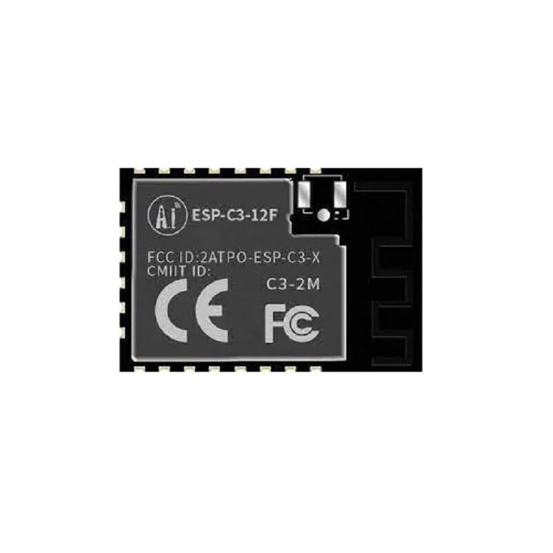
Ai-Thinker ESP32-C3-12F Wi-Fi + BLE Module
Best-value deep-sleep-capable Wi-Fi module for Indian battery IoT projects — PCB antenna version with 4MB flash, compatible with Arduino IDE.
Battery Life Calculator and Worked Examples
Use this formula for battery life estimation:
Battery Life (hours) = Battery Capacity (mAh) ÷ Average Current Draw (mA)
Average current draw over one duty cycle:
Avg Current = (I_active × T_active + I_sleep × T_sleep) ÷ (T_active + T_sleep)
Example 1: ESP8266, 15-minute reporting interval
- Active time: 4 seconds at 80mA average (Wi-Fi connect + send)
- Sleep time: 896 seconds at 20µA = 0.02mA
- Avg current = (80 × 4 + 0.02 × 896) ÷ 900 = (320 + 17.92) ÷ 900 = 0.375 mA
- 2000mAh 18650 battery: 2000 ÷ 0.375 = 5,333 hours ≈ 222 days
Example 2: ESP32, 5-minute reporting interval
- Active time: 3 seconds at 100mA average
- Sleep time: 297 seconds at 10µA = 0.01mA
- Avg current = (100 × 3 + 0.01 × 297) ÷ 300 = (300 + 2.97) ÷ 300 = 1.01 mA
- 2000mAh battery: 2000 ÷ 1.01 = 1,980 hours ≈ 82 days
Example 3: ESP32-C3, 1-hour reporting interval
- Active time: 2 seconds at 90mA
- Sleep time: 3598 seconds at 5µA = 0.005mA
- Avg current = (90 × 2 + 0.005 × 3598) ÷ 3600 = (180 + 17.99) ÷ 3600 = 0.055 mA
- 2000mAh battery: 2000 ÷ 0.055 = 36,364 hours ≈ 4.15 years
These calculations assume ideal conditions. In practice, reduce estimates by 30–40% to account for battery self-discharge, voltage regulator inefficiency, and temperature effects (Indian summer heat reduces Li-ion capacity significantly).
Hardware Tricks to Reduce Power Further
1. Remove the Power LED
Most ESP8266/ESP32 development boards have a red power LED connected to VCC through a 1kΩ resistor. This draws 2–3mA continuously — equivalent to 10× the deep sleep current. Desolder or cut this LED for battery-powered designs.
2. Remove or Bypass the USB-Serial Chip
CH340 and CP2102 chips draw 5–15mA when powered. In bare module designs (ESP-12, ESP-WROOM-02), this chip is absent. If using NodeMCU, the USB chip is always powered even during deep sleep.
3. Use a More Efficient Voltage Regulator
NodeMCU boards use AMS1117 LDOs with ~6mA quiescent current. Replace with an MCP1700 or XC6206 LDO (1–2µA quiescent) or an MP2305 switching regulator for large current reductions during sleep.
4. Disable Sensors During Sleep
Connect sensor VCC to a GPIO pin. Drive this pin HIGH before reading, then LOW before sleeping. This prevents sensors like DHT22, DS18B20, or soil moisture probes from drawing standby current during the deep sleep period.
5. Use Static IP Instead of DHCP
DHCP negotiation adds 200–500ms to Wi-Fi connection time. Configure a static IP on the ESP to skip DHCP, saving both time and energy per wake cycle.
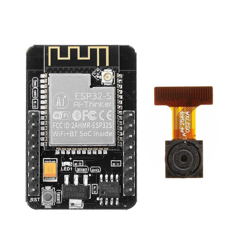
Ai Thinker ESP32 CAM Development Board WiFi+Bluetooth
For projects that need occasional camera snapshots alongside deep sleep sensor reporting — snap an image on wake, upload, then sleep again for days.
Which Module Should You Choose for Battery Projects?
| Requirement | Best Choice | Reason |
|---|---|---|
| Maximum battery life, hourly+ reporting | ESP32-C3 | 5µA deep sleep, RISC-V efficiency |
| Budget build, 15+ min reporting | ESP-12F (ESP8266) | Cheapest bare module, 20µA sleep |
| More processing power needed | ESP32 (WROOM-32) | Dual-core, 10µA sleep, ULP coprocessor |
| Prototype/learning project | NodeMCU ESP8266 | USB onboard, easiest to program |
| Need BLE alongside Wi-Fi | ESP32 or ESP32-C3 | ESP8266 has no Bluetooth |
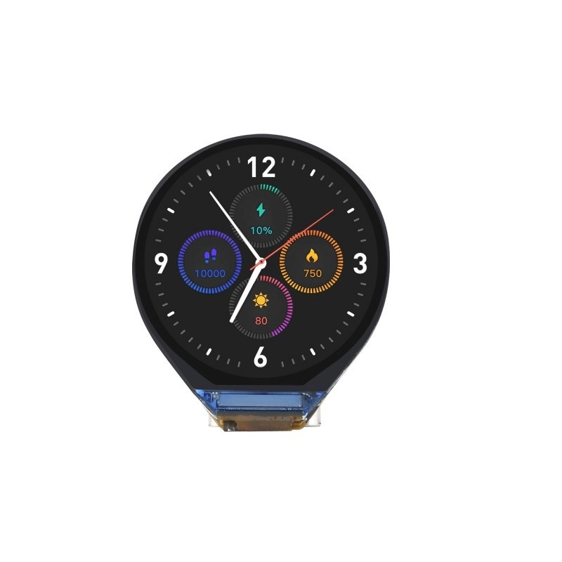
Waveshare ESP32-C3 0.71inch Round Display Development Board
Compact ESP32-C3 board with built-in round display — show sensor readings on wake, then sleep. Ideal for wearable or compact battery-powered IoT devices.
Frequently Asked Questions
Q: Why does my ESP8266 not wake up from deep sleep after connecting D0 to RST?
The D0 (GPIO16) to RST connection must be a direct short with a thin wire or 0Ω resistor — do not add any capacitors or long wires. Also ensure GPIO16 is not configured as an output in your sketch. If using NodeMCU, some boards have a 100nF capacitor on the RST line; remove it or add a 10kΩ pull-up on RST to let it recover from the brief LOW pulse.
Q: How long can ESP8266 sleep? What if I need more than 71 minutes?
The ESP8266 RTC timer is limited to approximately 71 minutes (4294967295 microseconds). For longer intervals, chain multiple sleep cycles by storing the remaining sleep count in RTC memory and checking it on each wake. Alternatively, use an external RTC module (DS3231) to trigger RST after arbitrary intervals.
Q: Does deep sleep work on NodeMCU boards or only bare ESP modules?
Deep sleep works on NodeMCU boards but the USB-serial chip (CH340/CP2102) stays powered and consumes 5–15mA during sleep. For true ultra-low-power applications, use a bare ESP-12F module without the development board’s USB chip. For learning and prototyping, NodeMCU deep sleep is fine — the overall sleep current is still much lower than active mode.
Q: Can I use a solar panel to charge the battery for an indefinitely running sensor node?
Yes. A 2W/6V solar panel with a TP4056 charging module and a 3.7V 2000mAh LiPo battery is a very popular combination among Indian IoT makers. In Indian sunlight conditions (4–6 peak sun hours per day), a 2W panel charges a 2000mAh battery in 2–3 days from empty while simultaneously powering a deep-sleep ESP32 node reporting every 15 minutes — a self-sustaining system.
Q: What is the ULP coprocessor on ESP32 and how does it help with power?
The ULP (Ultra-Low Power) coprocessor is a tiny processor that runs at ~150µA while the main ESP32 CPU is in deep sleep. It can read GPIO pins, access ADC, and even access I2C peripherals. Using the ULP, you can take analog sensor readings every minute without waking the main CPU — the ULP only wakes the main CPU when a threshold is crossed. This dramatically reduces power consumption for threshold-based alerting applications.
Build Battery-Powered IoT Nodes
Get ESP8266, ESP32, and ESP32-C3 modules for your deep sleep battery projects at Zbotic — quality wireless modules with fast delivery across India.


Add comment