
Powering a remote ESP32 project with solar energy is one of the most satisfying challenges in the maker world. Whether you’re building a weather station on your rooftop, a soil moisture monitor in your farm, or a wildlife camera in a forest reserve, combining solar power with ESP32, an MPPT controller, and a battery charging circuit gives you a truly self-sufficient, maintenance-free system. This guide walks Indian makers through every layer of the design — from panel selection to MPPT topology to firmware sleep strategies — so your next outdoor IoT node runs for years without intervention.
Why Solar + ESP32 Is a Perfect Pair
The ESP32 is India’s most popular microcontroller for IoT projects, and for good reason. It has built-in Wi-Fi and Bluetooth, dual-core processing, extensive GPIO, and — critically — a deep sleep mode that draws as little as 5–10µA. At that current draw, even a 1000mAh 18650 cell can last weeks between solar top-ups.
India’s solar irradiance averages 4–6 kWh/m²/day across most of the country — among the highest in the world. A 5W solar panel in Mumbai or Rajasthan can reliably generate 20–25Wh per day, which is more than enough to keep an ESP32-based sensor node running 24×7 with generous headroom.
The challenge is not the panel or the microcontroller — it’s the interface between them: the charging circuit and the MPPT controller. Get this right and your system runs indefinitely. Get it wrong and your batteries are either overcharged, chronically under-charged, or dead within a month.
Choosing the Right Solar Panel
For ESP32 sensor nodes, you typically need a small panel. Here’s how to size it:
- Average daily energy (Wh): Estimate your ESP32’s average power draw. A node that wakes every 30 minutes for 5 seconds (Wi-Fi active) might average 0.5–2mA at 3.7V ≈ 0.002–0.007Wh per day — far less than even a tiny 1W panel. A more demanding node with continuous MQTT streaming might need 30–100mAh/day.
- Panel voltage: Choose an open-circuit voltage (Voc) high enough to charge your battery in low-light conditions. For a single 3.7V 18650 cell, a 6V panel (Voc ~7.2V) is ideal. For a 2S pack (7.4V), use a 9V panel.
- Panel type: Monocrystalline panels are more efficient (18–22%) and perform better in low-light and high-temperature conditions, which makes them the better choice for India despite costing 20–30% more than polycrystalline.
- Weather and mounting: In monsoon-affected regions (most of India), size your panel 2–3× the theoretical minimum to account for cloudy days. Tilt the panel at your latitude angle (18–28° for most Indian cities) and orient it due south for maximum annual yield.
MPPT Explained: Squeezing Every Watt from Your Panel
A solar panel does not behave like a fixed voltage source. Its I-V curve changes with light intensity and temperature. There’s a specific point on this curve — the Maximum Power Point (MPP) — where the product of voltage and current (i.e., power) is maximised. Under a simple resistive load or a basic linear regulator, the panel operates far from this point, often wasting 20–30% of available energy.
MPPT (Maximum Power Point Tracking) is an algorithm implemented in a DC-DC converter that continuously adjusts its input impedance to keep the panel operating at or near its MPP. The most common algorithm is Perturb and Observe (P&O): the controller makes small changes to the operating voltage, measures whether power increased or decreased, and adjusts accordingly. More advanced algorithms include Incremental Conductance (INC) and Variable Step-Size methods that converge faster under rapidly changing light conditions.
MPPT ICs for DIY Builds
Several ICs make MPPT implementation accessible to makers:
- CN3791 / CN3722: Highly popular in India for small solar projects. Handles 1S/2S LiPo charging with integrated MPPT. Input up to 28V, charge current up to 4A. Available on breakout boards from local suppliers for ₹150–300.
- BQ24650 / BQ24074: Texas Instruments solar charge controllers with true MPPT. More precise, supports multiple battery chemistries, but requires more external components.
- SPV1040: Dedicated MPPT boost converter from STMicroelectronics. Useful for micro-panel inputs down to 0.3V — great for indoor light harvesting.
- LT3652: Analog Devices solar battery charger, extremely robust, used in industrial applications. Expensive but very reliable.
For a beginner ESP32 solar node, a CN3791-based module is the pragmatic choice. It handles the MPPT, charge regulation, and overcharge protection in a single package at low cost.
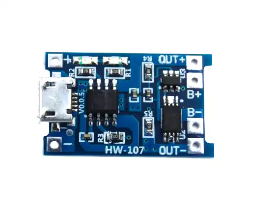
TP4056 1A Li-Ion Battery Charging Board with Current Protection
A compact and affordable charging module for single-cell 18650/Li-Ion batteries. While not a full MPPT controller, it works well as the final stage charger in a simple solar system where the MPPT IC outputs a regulated voltage to the TP4056 input.
Battery Charging Circuit Design
A complete solar-to-ESP32 charging circuit has several stages:
Stage 1: Panel → MPPT Converter
The panel feeds the MPPT IC (e.g., CN3791). The MPPT Voltage Set pin (MPPT_V) is connected to a resistor divider from the panel’s Voc. Set MPPT_V to 80% of Voc — this is a common approximation of the maximum power point voltage. For a 6V panel (Voc 7.2V), set MPPT_V ≈ 5.76V using a 100kΩ/22kΩ divider.
Stage 2: Charge Regulation
The MPPT IC’s output is connected to the battery. For a single 18650 cell, the IC sets the charge voltage to 4.2V (or 4.35V for high-capacity cells). The charge current is set by an external resistor. For a 2000mAh cell, use a C/2 rate (1A) for longevity; 500mA is gentler and preferred for long-term outdoor installations. Adjust the resistor value per the CN3791 datasheet (Rprog = 1000 / Ichrg for CN3791).
Stage 3: Battery → Load (ESP32 Supply)
The 3.7V battery feeds a boost converter or LDO regulator to power the ESP32. The ESP32 requires 3.3V at 0.5A peak (during Wi-Fi transmission). A small boost/buck-boost IC like the TPS63020 or ME2149 handles the battery voltage variation from 3.0V (depleted) to 4.2V (full) and outputs a clean 3.3V. Avoid using a simple diode from battery to 3.3V — the voltage drop wastes energy and the output voltage varies with charge state.
Stage 4: Low-Battery Protection
Add a comparator circuit or use the battery’s BMS to cut the load when cell voltage drops below 3.0V per cell. Deep-discharging a lithium cell below 2.5V permanently damages it. The BMS protection board handles this automatically.

1S 18650 Li-ion Lithium Battery BMS Charger Protection Board
This BMS board provides over-charge, over-discharge, over-current, and short-circuit protection for your solar node’s 18650 battery. An essential safety layer between your charging circuit and the cell.
ESP32 Power Management and Deep Sleep
The MPPT and charging circuit determine how much energy you harvest. The ESP32’s firmware determines how much you spend. The ratio between these two numbers is everything.
Deep Sleep Mode
The ESP32’s deep sleep mode cuts power to everything except the RTC (Real-Time Clock) module, selected GPIOs, and the ULP (Ultra-Low-Power) co-processor. Current draw drops from ~150mA (active Wi-Fi) to 5–10µA — a reduction of 15,000×. Use esp_deep_sleep_start() after completing each sensor reading and data transmission cycle.
// Wake every 30 minutes
#define SLEEP_DURATION_US 1800000000ULL
esp_sleep_enable_timer_wakeup(SLEEP_DURATION_US);
esp_deep_sleep_start();
Reducing Active-Mode Power
- Use ESP-NOW instead of Wi-Fi MQTT where possible — it reduces active TX time from ~500ms to ~10ms.
- Lower CPU frequency:
setCpuFrequencyMhz(80)reduces active power by ~40% vs 240MHz for sensor read tasks. - Disable Bluetooth if not used:
btStop()saves ~10mA. - Use a dedicated RTC chip (DS3231) for accurate timing rather than relying on the ESP32’s internal timer, which drifts during deep sleep and wastes power on NTP sync.
Energy Budget Example
A node that wakes every 30 minutes, reads a DHT22 temperature/humidity sensor (200ms), connects to Wi-Fi (3 seconds), publishes MQTT, then goes back to sleep:
- Active period: 3.5 seconds at 160mA = 0.155mAh
- Sleep period: 29 minutes 56.5 seconds at 8µA = 0.004mAh
- Total per cycle: ~0.16mAh; total per day: ~7.7mAh
- A 2000mAh cell provides 260 days of operation — but charge it daily with even a 0.5W panel and you have indefinite runtime.
Complete System Design Example
Here’s a practical Bill of Materials for a solar-powered ESP32 weather station deployable in an Indian field or rooftop setting:
| Component | Part/Value | Cost (approx.) |
|---|---|---|
| Solar panel | 5W 6V Monocrystalline | ₹250–400 |
| MPPT charger IC module | CN3791 breakout | ₹150–300 |
| Battery | 18650 2500mAh (genuine Sanyo/LG) | ₹350–500 |
| BMS | 1S 3A BMS | ₹30–60 |
| Boost converter | MT3608 3.3V output, or TPS63020 | ₹40–200 |
| Microcontroller | ESP32 DevKit or ESP32-C3 | ₹200–400 |
| Sensor | BME280 (temp/humidity/pressure) | ₹150–250 |
| Enclosure | IP65 ABS junction box | ₹80–150 |
| Total | ₹1,250–2,260 |
This system will run indefinitely under normal Indian sunlight conditions, transmitting sensor data every 30 minutes to an MQTT broker or Google Sheets via a home router.

1S 12A 3.6V BMS Battery Protection Board for Li-ion Cell
Higher-current BMS ideal for solar nodes that power additional peripherals like relay outputs, pumps, or display modules alongside the ESP32. 12A continuous rating provides ample headroom.

1 x 18650 Battery Holder (18.4mm Bore) – Pack of 4
Securely mount your solar node’s 18650 battery with this durable holder. The 18.4mm bore fits all standard 18650 cells, and the pack of 4 lets you configure multi-cell storage arrays.
Frequently Asked Questions
Can I use the TP4056 module directly with a solar panel?
Yes, but without MPPT. The TP4056 is a linear charger — it works when input voltage is above 4.5V. Connect a 6V solar panel directly to its input, and it will charge a 1S lithium cell. However, in low-light conditions, the panel voltage may drop below the TP4056’s minimum input, stopping the charge. An MPPT controller maintains charging even at reduced light levels. For small, non-critical projects, the TP4056 + solar panel is perfectly acceptable.
How do I protect the circuit from lightning strikes in outdoor installations?
Add a TVS (transient voltage suppressor) diode and a gas discharge tube (GDT) at the solar panel input. MOV-based surge protectors designed for 12V DC systems are also available cheaply in India. Always earth/ground the panel frame and enclosure.
What’s the difference between PWM and MPPT solar controllers?
PWM controllers connect the panel directly to the battery through a switch — they are simple and cheap but inefficient (especially when panel voltage is much higher than battery voltage). MPPT controllers use a DC-DC converter to continuously track the panel’s maximum power point and can be 15–30% more efficient, particularly during morning/evening hours and on cloudy days.
Can the ESP32 measure its own battery voltage?
Yes. Connect the battery positive through a resistor divider (100kΩ + 100kΩ) to an ADC pin. The ESP32’s ADC is not highly linear but is accurate enough for battery state estimation. Use a 100nF capacitor on the ADC pin to reduce noise. Calibrate the ADC offset using known reference voltages.
Is it safe to leave the system unattended outdoors for months?
Yes, provided you use a proper BMS with overcharge/overdischarge protection, waterproof the enclosure (IP65 minimum), and choose a cell chemistry suitable for high temperatures (LFP cells handle 60°C better than NMC/NCA). Indian summer temperatures inside an unventilated black enclosure can exceed 70°C — use a vented or white-painted enclosure.
Power Your Next IoT Project with the Sun
Combining solar panels, MPPT charging, 18650 cells, and the ESP32’s deep sleep capability opens up a whole world of maintenance-free outdoor IoT. The total system cost is under ₹2,000 for most applications — cheaper than running a power cable and far more versatile. Browse Zbotic’s Batteries & Power range to pick up BMS boards, charging modules, and battery holders for your next solar ESP32 build.


Add comment