
HC-05 Bluetooth Serial Bridge: Wireless Arduino Programming
If you have ever struggled with tangled USB cables while debugging an Arduino project or wished you could reprogram your microcontroller without reaching behind a panel, the HC-05 Bluetooth serial bridge for Arduino is the answer. This compact, affordable module lets you replace the physical USB-to-serial connection with a wireless Bluetooth link — enabling you to upload sketches, run the Serial Monitor, and debug your projects entirely over the air. In this guide, we cover everything from hardware wiring to AT command configuration and a practical wireless programming demo tailored for Indian hobbyists.
What is the HC-05 Bluetooth Module?
The HC-05 is a classic SPP (Serial Port Profile) Bluetooth 2.0 module that operates in the 2.4 GHz ISM band. Unlike the HC-06 (slave only), the HC-05 can be configured as either a master or slave, making it ideal for point-to-point wireless serial communication. Its default baud rate is 9600 bps, it has an onboard LED indicator, and it communicates with a host microcontroller through a straightforward UART interface using just four wires: VCC, GND, TX, and RX.
Key specifications at a glance:
- Bluetooth version: 2.0 + EDR, Class 2
- Range: up to 10 metres (30+ metres in open air)
- Operating voltage: 3.3V logic (5V tolerant on most modules via built-in regulator)
- Default baud rate: 9600 bps (configurable via AT commands up to 1382400 bps)
- Pairing PIN: 1234 (default)
- Current draw: ~30 mA during transmission, ~8 mA idle
At roughly ₹150–₹200 at Zbotic, the HC-05 is one of the most cost-effective wireless communication modules available to Indian makers.
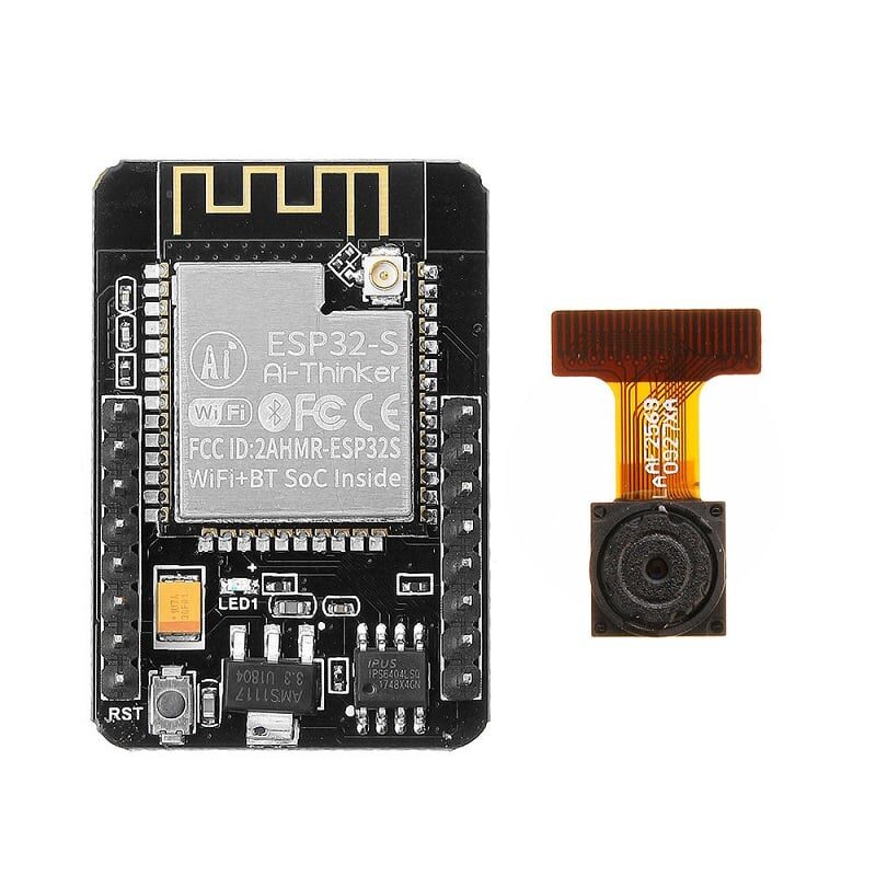
Ai Thinker ESP32 CAM – WiFi + Bluetooth Development Board
Need both WiFi and Bluetooth in one board? The ESP32-CAM packs dual wireless protocols plus a camera — perfect for advanced wireless projects beyond HC-05.
Wiring HC-05 to Arduino
The HC-05 module runs on 3.3V logic. Most Arduino boards (Uno, Nano, Mega) output 5V on their TX pins. While many HC-05 modules tolerate 5V on the RX pin due to an onboard regulator, it is safer to use a voltage divider (two resistors: 1kΩ and 2kΩ) on the Arduino TX → HC-05 RX line.
Hardware connections (Arduino Uno / Nano)
| HC-05 Pin | Arduino Pin | Notes |
|---|---|---|
| VCC | 5V | Module has onboard 3.3V regulator |
| GND | GND | Common ground |
| TXD | D10 (SoftSerial RX) | Direct connection safe |
| RXD | D11 (SoftSerial TX) via 1k+2k divider | Voltage divider recommended |
For the serial bridge use-case (where you want to replace the USB cable entirely), you must use the hardware serial pins (D0/D1 on Uno or a dedicated UART on Mega) and disconnect them before uploading. On Arduino Mega, UART1 (pins 18/19) is ideal since it leaves UART0 free for USB.
AT Command Configuration
Before using the HC-05 as a serial bridge, you need to configure it via AT commands. To enter AT mode, hold the small button on the module (or pull EN/KEY pin HIGH) while powering it on. The LED will blink slowly (~2 seconds interval) confirming AT mode.
Open the Serial Monitor in Arduino IDE at 38400 baud with Both NL & CR line ending selected.
Essential AT Commands
AT                    // Test connection — responds OK
AT+NAME?              // Query device name
AT+NAME=ZBOTIC_BT     // Set device name
AT+PSWD?              // Query pairing PIN
AT+PSWD=1234          // Set PIN (default is already 1234)
AT+UART?              // Query baud rate
AT+UART=115200,0,0    // Set baud to 115200 (match your sketch)
AT+ROLE?              // 0 = Slave, 1 = Master
AT+ROLE=0             // Set as slave (for PC/phone connections)
AT+RESET              // Reboot module
For the serial bridge project, set the baud rate to match the Arduino IDE’s upload baud rate. Arduino Uno uses 115200 bps for sketch uploads via avrdude.
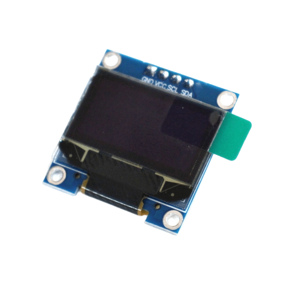
0.96 Inch I2C OLED Display – SSD1306 (White)
Pair this tiny OLED display with your Arduino + HC-05 project to show Bluetooth connection status, sensor readings, or debug info wirelessly.
Setting Up the Bluetooth Serial Bridge
The serial bridge mode means your PC’s Bluetooth stack sees the HC-05 as a virtual COM port (e.g. COM5 on Windows, /dev/rfcomm0 on Linux). Arduino IDE can then use this virtual port exactly like a USB connection.
Step 1 – Pair HC-05 with your PC
- Power the Arduino + HC-05. LED blinks fast in normal mode.
- On Windows: open Bluetooth settings → Add device → find your HC-05 name → enter PIN 1234.
- After pairing, check Device Manager for the new COM port under Ports (COM & LPT).
- On Linux:
sudo rfcomm bind 0 XX:XX:XX:XX:XX:XX 1creates /dev/rfcomm0.
Step 2 – Upload a sketch with the bridge
For wireless upload to work, the Arduino must be running a bootloader-compatible bridge. The simplest approach uses Arduino Mega’s UART1:
// Bridge sketch for Arduino Mega (UART0 ↔ UART1 passthrough)
void setup() {
  Serial.begin(115200);   // USB (UART0) — for initial upload
  Serial1.begin(115200);  // HC-05 connected to pins 18/19
}

void loop() {
  if (Serial.available())  Serial1.write(Serial.read());
  if (Serial1.available()) Serial.write(Serial1.read());
}
After uploading this via USB, you can then select the Bluetooth COM port in Arduino IDE and upload subsequent sketches wirelessly. Note: the DTR/reset signal required for auto-reset does not travel over Bluetooth, so you may need to manually press the Reset button on the Arduino just as the IDE starts uploading (watch for the Uploading… message).
Using the Wireless Serial Monitor
Even without full wireless upload, the most practical daily use of the HC-05 serial bridge is the wireless Serial Monitor. This lets you read sensor data, debug output, and send commands from your laptop while the Arduino is mounted in a robot, wall enclosure, or remote panel.
#include <SoftwareSerial.h>

SoftwareSerial btSerial(10, 11); // RX=10, TX=11

void setup() {
  Serial.begin(9600);     // USB Serial Monitor
  btSerial.begin(9600);   // HC-05 (default 9600 bps)
  Serial.println("Bluetooth Serial Bridge Ready");
}

void loop() {
  // Echo data from Bluetooth to USB Serial Monitor
  if (btSerial.available()) {
    char c = btSerial.read();
    Serial.write(c);
  }
  // Send Serial Monitor input to Bluetooth device
  if (Serial.available()) {
    char c = Serial.read();
    btSerial.write(c);
  }

  // Example: send a sensor reading every second
  static unsigned long last = 0;
  if (millis() - last > 1000) {
    last = millis();
    int val = analogRead(A0);
    btSerial.print("Sensor A0: ");
    btSerial.println(val);
  }
}
Open the Bluetooth COM port in Serial Monitor (or any terminal app like PuTTY / CoolTerm). You will see live sensor readings as if the USB cable were plugged in — great for testing deployed devices.
Controlling Arduino from an Android App
Indian makers widely use apps like Serial Bluetooth Terminal (free on Play Store) or the Dabble app to control Arduino wirelessly. Here is a simple LED toggle example:
#include <SoftwareSerial.h>

SoftwareSerial bt(10, 11);
const int LED = 13;

void setup() {
  bt.begin(9600);
  pinMode(LED, OUTPUT);
}

void loop() {
  if (bt.available()) {
    char cmd = bt.read();
    if (cmd == '1') {
      digitalWrite(LED, HIGH);
      bt.println("LED ON");
    } else if (cmd == '0') {
      digitalWrite(LED, LOW);
      bt.println("LED OFF");
    } else if (cmd == 's') {
      bt.print("Temp: ");
      bt.println(analogRead(A0) * 0.48, 1); // rough LM35 reading
    }
  }
}
Send ‘1’ from the app to turn the LED on, ‘0’ to turn it off, and ‘s’ to request a sensor reading. This pattern scales easily to relay control, motor commands, or IoT dashboards.
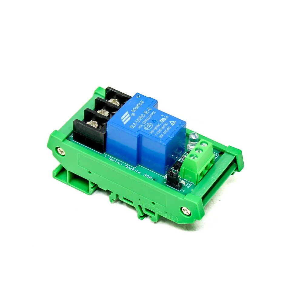
1 Channel 12V 30A Relay Module with Optocoupler
Control heavy 12V loads wirelessly via HC-05 and Arduino with this industrial-grade optocoupler relay module rated at 30A.
Common Issues and Fixes
HC-05 not pairing
Ensure the module is in normal mode (fast blinking LED). If LED is off, check VCC — the module needs a stable 3.6–6V supply. Weak USB power banks can cause dropouts.
Garbled characters in Serial Monitor
Baud rate mismatch is the most common cause. Ensure the baud rate in your sketch, AT command setting, and Serial Monitor all match. Use AT+UART? to confirm the module’s current setting.
Upload fails over Bluetooth
avrdude requires the DTR line to auto-reset the Arduino. Over Bluetooth this signal is absent. Solution: manually press Reset at the exact moment the IDE prints Uploading…, or use the -D flag in avrdude to skip erase and enable no-reset upload.
Interference with 2.4 GHz WiFi
HC-05 uses the same 2.4 GHz band as WiFi. In dense apartment blocks in Indian cities, interference can cause dropped characters. Consider using HC-05 on a dedicated channel via AT+RMAAD and AT+CMODE commands, or upgrade to an HC-06 with frequency hopping disabled on your router.
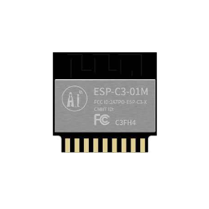
Ai Thinker ESP32-C3-01M Wi-Fi + BLE Module
Looking to upgrade from HC-05? The ESP32-C3 module offers both WiFi and BLE 5.0 at a comparable price — with full OTA (over-the-air) programming built in.
Frequently Asked Questions
Can I upload Arduino sketches wirelessly using HC-05?
Yes, but it requires a manual Reset press during upload since Bluetooth does not carry the DTR signal needed for auto-reset. It works reliably on Arduino Mega using a UART passthrough sketch on UART1.
What is the difference between HC-05 and HC-06?
The HC-06 is slave-only and has a simpler AT command set. The HC-05 supports both master and slave roles, making it more versatile for device-to-device communication. For Android app control, either works; for bridging two Arduinos wirelessly, you need at least one HC-05 in master mode.
What range can I expect from HC-05 indoors?
Typically 8–10 metres through walls in a typical Indian apartment. In open air or without obstructions, 20–30 metres is achievable. For longer ranges, consider nRF24L01+ (100m) or LoRa (kilometres).
Is HC-05 compatible with iOS devices?
No. HC-05 uses the Bluetooth Classic SPP profile which is not accessible to third-party apps on iOS. For iOS compatibility, you need BLE (Bluetooth Low Energy) modules like HM-10 or an ESP32 in BLE mode.
Can I use HC-05 to make two Arduinos talk to each other?
Yes. Configure one HC-05 as master (AT+ROLE=1) and the other as slave (AT+ROLE=0). The master automatically connects to the slave’s address (AT+BIND). Once paired, data flows transparently between the two UART lines — as if they were connected by a wire.


Add comment