
The RS232 to TTL MAX3232 Arduino converter is an essential tool for any maker who works with industrial equipment, legacy computers, PLCs, or serial communication devices that predate the USB era. RS232 is a 40-year-old standard that still powers cash registers, industrial sensors, barcode readers, GPS receivers, and countless other devices worldwide — including many you’ll find in Indian factories, warehouses, and labs. This tutorial explains what RS232 is, how the MAX3232 translates it to microcontroller-friendly TTL levels, and how to use it with Arduino for practical projects.
RS232 vs TTL: The Voltage Gap That Matters
Serial communication (UART) works by toggling a signal line between a logic HIGH and logic LOW state to represent 1s and 0s. The fundamental problem between RS232 and TTL logic is that they define these states at completely different voltage levels:
| Signal | RS232 Voltage | TTL 5V Voltage | TTL 3.3V Voltage |
|---|---|---|---|
| Logic HIGH (0 / Space) | +3V to +15V | +2V to +5V | +2V to +3.3V |
| Logic LOW (1 / Mark) | -3V to -15V | 0V to +0.8V | 0V to +0.8V |
Notice the critical difference: RS232 uses negative voltages (down to -15V) to represent a logic 1 (MARK state). If you connect a PC’s RS232 port directly to an Arduino’s RX pin, you’ll apply -12V to a 5V logic input — destroying the microcontroller instantly.
The MAX3232 IC exists to translate between these two worlds safely. It converts RS232’s ±12V signals to 3.3V TTL levels (and vice versa) using internal charge pumps, requiring only a single 3.3V power supply.
The MAX3232 IC: How It Works
The MAX3232 (and its 5V cousin, the MAX232) contains two key circuits:
- Charge pump voltage multiplier/inverter: Generates ±10V internally from the 3.3V supply using external capacitors (100nF typically). This provides the voltage rails needed to drive RS232 output lines.
- Level translators: Two transmitter channels (TTL in → RS232 out) and two receiver channels (RS232 in → TTL out) with built-in input protection.
The MAX3232 differs from the older MAX232 in its supply voltage: MAX232 requires 5V, while MAX3232 works at 3.0V–5.5V, making it compatible with both 3.3V (ESP32, STM32) and 5V (Arduino Uno) systems.
Choosing Between MAX232 and MAX3232
- Use MAX232 with Arduino Uno/Mega (5V systems) — slightly cheaper, works well
- Use MAX3232 with ESP32, STM32, Raspberry Pi (3.3V systems) — recommended modern choice
- Both are pin-compatible and available as pre-built breakout modules
Module Pinout & Wiring Guide
Pre-built MAX3232 breakout modules (available from Zbotic) typically expose these pins:
RS232 Side (connects to DB9 serial port):
- RS232-RX: Receives data from RS232 device (pin 2 on DB9 female)
- RS232-TX: Transmits data to RS232 device (pin 3 on DB9 female)
- GND: Signal ground (pin 5 on DB9 female)
TTL Side (connects to Arduino/microcontroller):
- TTL-RX: Receives TTL data from microcontroller TX → converts to RS232
- TTL-TX: Transmits TTL data to microcontroller RX ← from RS232
- VCC: 3.3V or 5V power supply
- GND: Ground
DB9 Connector Pin Reference:
| DB9 Pin | Signal | Direction (DTE → DCE) |
|---|---|---|
| 1 | DCD (Data Carrier Detect) | Input |
| 2 | RXD (Receive Data) | Input |
| 3 | TXD (Transmit Data) | Output |
| 4 | DTR (Data Terminal Ready) | Output |
| 5 | GND (Signal Ground) | — |
| 6 | DSR (Data Set Ready) | Input |
| 7 | RTS (Request to Send) | Output |
| 8 | CTS (Clear to Send) | Input |
For basic data transfer, you only need pins 2 (RXD), 3 (TXD), and 5 (GND). Hardware flow control pins (RTS/CTS/DTR/DSR) can often be shorted together or left unconnected depending on the device.
Connecting to Arduino: Step-by-Step
Here is how to connect a MAX3232 module between an Arduino Uno and a PC or RS232 device:
MAX3232 Module ↔ Arduino Uno:
- Module VCC → Arduino 5V (MAX3232 supports 3.3–5.5V)
- Module GND → Arduino GND
- Module TTL-RX → Arduino pin 10 (if using SoftwareSerial TX) or Arduino TX (pin 1 for HardwareSerial)
- Module TTL-TX → Arduino pin 11 (if using SoftwareSerial RX) or Arduino RX (pin 0 for HardwareSerial)
MAX3232 Module ↔ DB9 Device/PC:
- Module RS232-TX → DB9 pin 2 (RXD of the PC/device)
- Module RS232-RX → DB9 pin 3 (TXD of the PC/device)
- Module GND → DB9 pin 5
Important note on TX/RX crossover: The classic RS232 rule is that TX from one side connects to RX of the other. This is called a straight-through cable for DTE-DCE connections (PC to modem/sensor). For DTE-DTE connections (PC to PC, Arduino to PC), you need a null modem cable that crosses TX↔RX and swaps handshaking lines. Most ready-made MAX3232 modules already handle the basic crossover, but verify with your specific device.
Arduino Sketch for RS232 Communication
Here’s a practical Arduino sketch using SoftwareSerial to communicate with an RS232 device while keeping the USB serial port for debugging:
#include <SoftwareSerial.h>

// MAX3232 TTL side: pin 10 = RX (receives from MAX3232 TTL-TX)
//                   pin 11 = TX (sends to MAX3232 TTL-RX)
SoftwareSerial rs232Serial(10, 11);

void setup() {
  Serial.begin(9600);     // USB debug serial
  rs232Serial.begin(9600); // Must match RS232 device baud rate
  Serial.println("RS232 Bridge Ready");
  Serial.println("Type in Serial Monitor to send to RS232 device");
}

void loop() {
  // Forward USB Serial → RS232 device
  if (Serial.available()) {
    char c = Serial.read();
    rs232Serial.write(c);
  }

  // Forward RS232 device → USB Serial
  if (rs232Serial.available()) {
    char c = rs232Serial.read();
    Serial.write(c);
  }
}
This creates a transparent bridge — whatever you type in Arduino Serial Monitor gets sent to the RS232 device, and its responses appear in Serial Monitor. Change the baud rate in both Serial.begin() and rs232Serial.begin() to match your specific RS232 device (common rates: 4800, 9600, 19200, 115200).
Reading a Specific RS232 Device (Barcode Scanner Example)
void loop() {
  // Barcode scanners send data terminated by CR (r) or CR+LF (rn)
  if (rs232Serial.available()) {
    String barcode = rs232Serial.readStringUntil('r');
    barcode.trim(); // Remove whitespace/CR/LF
    if (barcode.length() > 0) {
      Serial.print("Barcode scanned: ");
      Serial.println(barcode);
      // Process barcode — lookup in array, trigger relay, etc.
      processBarcode(barcode);
    }
  }
}

void processBarcode(String code) {
  // Your logic here — display on OLED, log to SD card,
  // send to server via GSM, activate relay, etc.
  Serial.println("Processing: " + code);
}
Real-World Use Cases in India
1. Reading Industrial Weighing Scales
Most industrial weighing scales used in Indian warehouses, textile mills, and logistics companies output data via RS232 at 9600 or 19200 baud. With a MAX3232 module, you can read weight data into Arduino, log it to an SD card, display it on a screen, or upload it to an ERP system via Wi-Fi (ESP32) or GSM.
2. Legacy PLC Integration
Older Siemens S7-200, Allen-Bradley, and OMRON PLCs use RS232 programming ports. MAX3232 converters allow modern microcontrollers to read process data from these legacy systems, bridging them into modern IoT architectures without replacing expensive hardware.
3. Barcode Scanner Integration
Many industrial barcode scanners (Datalogic, Honeywell, Zebra older models) output scanned codes via RS232. A MAX3232 module connected to Arduino enables automated inventory counting, production line tracking, and access control systems using these existing scanners.
4. GPS Receiver NMEA Output
Some older GPS receivers (used in survey equipment, agricultural GPS systems) output NMEA 0183 data at RS232 levels rather than TTL. A MAX3232 module allows Arduino to parse this GPS data for custom positioning applications.
5. Connecting to PC for Data Logging
If you have sensor data in an Arduino and want to log it to a legacy PC or industrial computer with only a DB9 RS232 port (no USB), the MAX3232 module converts Arduino’s TTL UART to RS232 for direct connection to the PC’s COM port. Terminal programs like PuTTY, CoolTerm, or RealTerm on Windows receive and log the data.
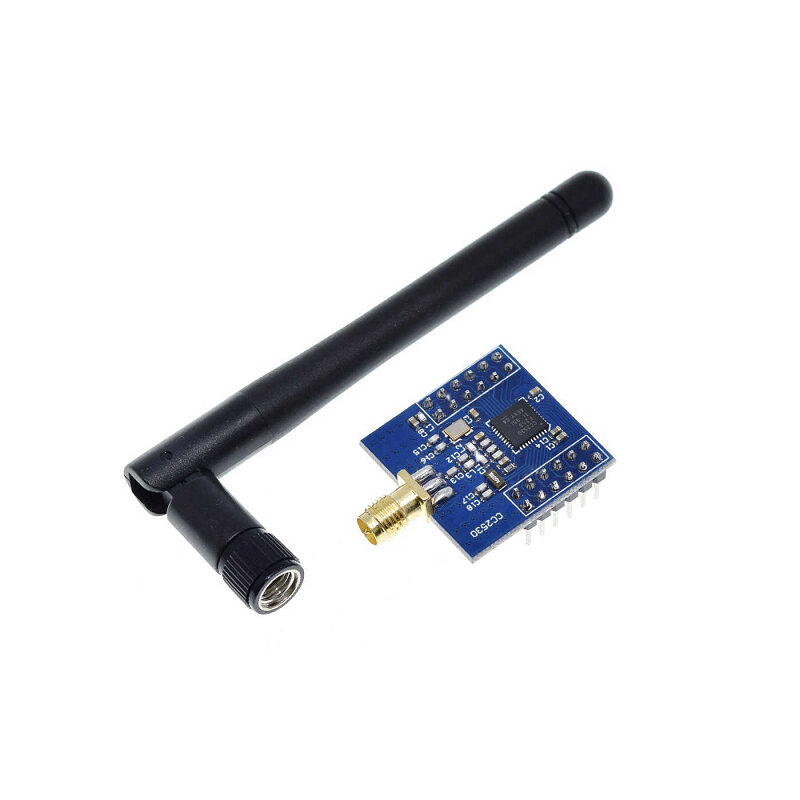
CC2530F256 Zigbee UART Wireless Core Board
Combine RS232-to-TTL conversion with Zigbee wireless: read RS232 industrial device data via MAX3232, then transmit wirelessly via this CC2530 Zigbee module over UART. Build wireless industrial sensor networks from legacy RS232 equipment.
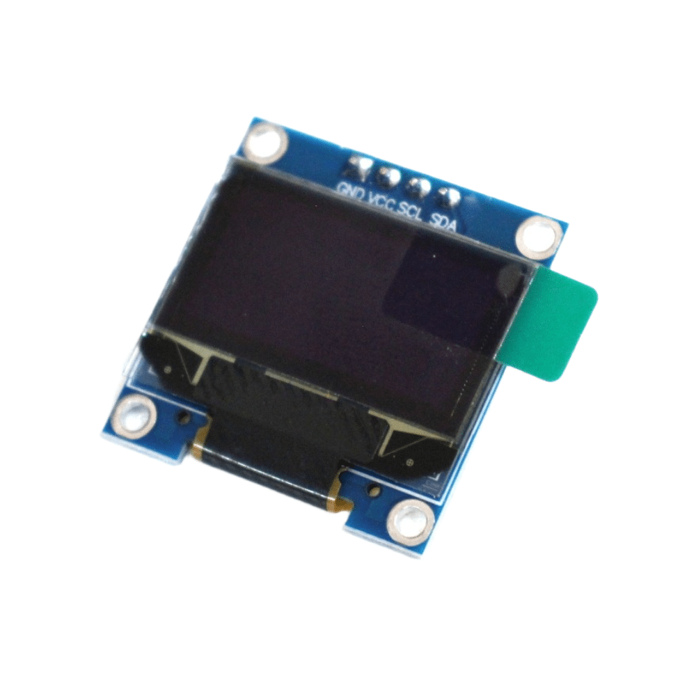
0.96 Inch I2C OLED Display (SSD1306)
Display RS232 device output in real time — weighing scale readings, barcode data, PLC status — on this compact OLED screen connected to your Arduino over I2C. Perfect for a standalone RS232 data display terminal.
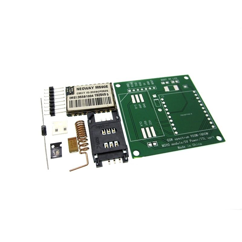
DIY GSM/GPRS M590E Module Kit
Take RS232 data wireless: read from legacy industrial equipment via MAX3232, process with Arduino, then upload via this GSM/GPRS module to a cloud server or send SMS alerts. Build a complete industrial IoT bridge without replacing existing equipment.
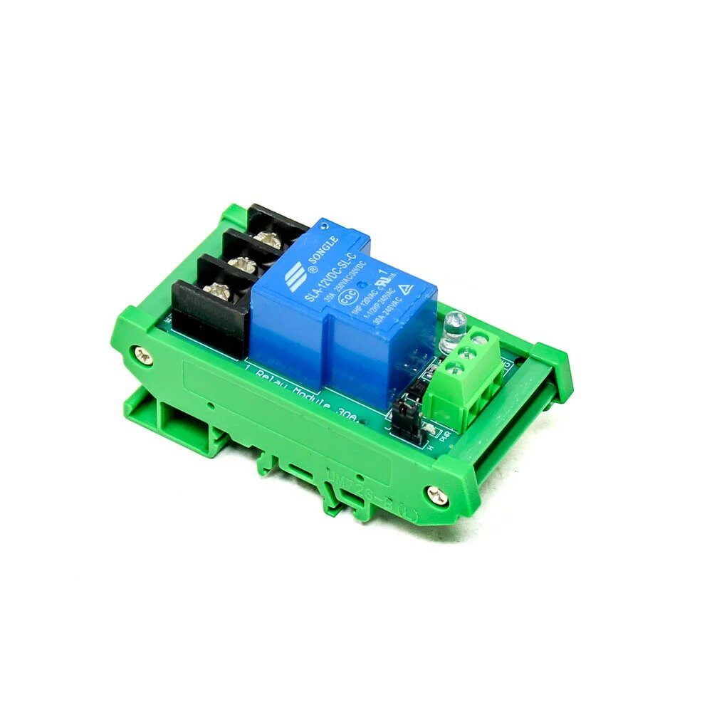
1 Channel 12V 30A Relay Module with Optocoupler
Control industrial loads based on RS232 commands received by Arduino. This heavy-duty 30A relay module with optocoupler isolation is ideal for switching industrial equipment, motors, or machinery based on RS232 trigger signals from a PLC or computer.
Troubleshooting RS232 Issues
No data received from RS232 device
- Verify baud rate matches the RS232 device specification exactly. Common mismatch: device at 19200 while Arduino is at 9600.
- Check TX/RX crossover — the module’s RS232-TX should connect to the device’s RXD pin, not its TXD pin.
- Some RS232 devices require RTS/CTS handshaking to be enabled or shorted before they’ll transmit. Short pin 7 (RTS) to pin 8 (CTS) and pin 4 (DTR) to pin 6 (DSR) on the DB9 to bypass hardware flow control.
Garbled data / random characters
- Wrong baud rate is the most common cause. Try 4800, 9600, 19200, 38400, 57600, 115200 systematically.
- Parity or stop bit mismatch. RS232 communication requires both sides to agree on data bits (usually 8), parity (usually None), and stop bits (usually 1) — commonly written as 8N1.
- Ground not connected — ensure the GND wire between module and RS232 device is firmly connected.
Module gets hot or doesn’t power on
- Check VCC voltage — MAX3232 modules are typically 3.3V; some breakouts accept 5V. Applying 5V to a 3.3V-only module will damage it.
- Ensure the external capacitors on the MAX3232 IC are properly soldered if you’re using a bare IC rather than a module.
Frequently Asked Questions
What is the difference between MAX232 and MAX3232?
The MAX232 requires a 5V power supply and uses 1µF electrolytic capacitors externally. The MAX3232 operates from 3.0V to 5.5V, uses smaller 100nF (0.1µF) capacitors, and is fully compatible with 3.3V systems like ESP32, STM32, and Raspberry Pi. For Arduino Uno (5V), either works; for modern 3.3V microcontrollers, always use MAX3232 to avoid needing a 5V supply just for the converter.
Can I use an ESP32 instead of Arduino with MAX3232?
Yes. The MAX3232 operates at 3.3V, which matches ESP32’s logic levels exactly. Connect ESP32 UART2 (GPIO16 = RX, GPIO17 = TX) to the MAX3232’s TTL-RX and TTL-TX respectively. Use Serial2.begin(9600) in your ESP32 sketch. The ESP32 adds Wi-Fi capability, making it excellent for wirelessly relaying RS232 device data to a cloud server or MQTT broker.
Do I need a null modem cable between two Arduinos?
When connecting two Arduino systems via RS232 (both acting as DTE), you need a null modem cable that crosses TX↔RX (pin 3 → pin 2 and pin 2 → pin 3) and links the handshaking lines appropriately. For simplest connection, just cross the TX and RX wires and tie RTS to CTS on each side to simulate hardware flow control locally.
How do I find the COM port settings for my RS232 device?
Check the device’s manual or front panel settings menu for baud rate, data bits, parity, and stop bits. If undocumented, start with 9600 8N1 (the most common setting for industrial devices in India). If that gives no response, try 19200 8N1, then 115200 8N1. Use a logic analyser or RS232 sniffer software on a PC to capture the raw signal and determine the baud rate automatically.
Can MAX3232 handle RS422 or RS485?
No. MAX3232 is designed specifically for RS232 (single-ended, point-to-point). RS422 is differential and supports longer cables; RS485 is differential and supports multi-drop networks (up to 32 devices). These require different ICs — the MAX485 for RS485, and MAX3491 for RS422. If your industrial device uses RS485 (common in Modbus applications), you’ll need a dedicated RS485-to-TTL module, not the MAX3232.
Bridge Old and New Technology with Zbotic
Zbotic stocks serial communication modules, relay boards, displays, and wireless modules to help you modernise legacy industrial equipment. Fast delivery across India.


Add comment