
OLED Display Not Working: I2C Address & Library Troubleshoot
You have wired up your 0.96″ OLED, uploaded the sketch, and… nothing. A blank screen stares back at you. If your OLED display is not working and you need an I2C fix, you are not alone — this is one of the most common frustrations for makers using SSD1306 or SH1106 128×64 displays with Arduino. The good news is that 95% of OLED failures have simple, fixable causes. This troubleshooting guide walks through every possible reason your OLED is not displaying, with step-by-step fixes for each scenario.
Quick Pre-Diagnosis Checklist
Before diving into detailed debugging, run through this quick checklist. Most OLED failures are caught at this stage:
- Is the OLED module receiving power? (Check VCC pin with a multimeter — should read 3.3V or 5V depending on module)
- Are SDA and SCL wires connected to the correct Arduino pins? (A4 = SDA, A5 = SCL on Uno/Nano)
- Have you confirmed the I2C address in your code matches the actual module address?
- Did you install the correct library for your specific OLED driver IC (SSD1306 vs SH1106)?
- Is the display selected for I2C mode? (Some modules have I2C/SPI solder bridge — check with magnifying glass)
If all of the above checks out and the display still does not work, proceed with the detailed steps below.
Run the I2C Scanner First
This is the single most valuable diagnostic step. The I2C scanner sketch tells you whether your Arduino can even detect the OLED on the bus. If the scanner does not find any device, the problem is hardware (wiring, power, or dead module). If it finds a device at an unexpected address, your code has the wrong address.
#include <Wire.h>

void setup() {
  Wire.begin();
  Serial.begin(9600);
  while (!Serial); // Wait for serial on Leonardo/Micro

  Serial.println("--- I2C Scanner ---");
  byte deviceCount = 0;

  for (byte addr = 1; addr < 127; addr++) {
    Wire.beginTransmission(addr);
    byte err = Wire.endTransmission();

    if (err == 0) {
      Serial.print("Device at 0x");
      if (addr < 16) Serial.print("0");
      Serial.println(addr, HEX);
      deviceCount++;
    }
  }

  if (deviceCount == 0)
    Serial.println("No I2C devices found!");
  else
    Serial.println("Scan complete.");
}

void loop() {}
Upload this, open Serial Monitor at 9600 baud, and press the reset button. Expected output for a working OLED:
Device at 0x3C— Most common default addressDevice at 0x3D— Some modules (when ADDR pin is HIGH)
If you see “No I2C devices found!” — the problem is hardware. Check wiring and power.
Wrong I2C Address: 0x3C vs 0x3D
The I2C address of SSD1306 OLED modules is determined by the SA0 (also called ADDR or DC) pin or solder jumper on the PCB:
| SA0/ADDR Pin State | I2C Address | Notes |
|---|---|---|
| LOW (GND) | 0x3C | Default on almost all cheap modules |
| HIGH (VCC) | 0x3D | Secondary address, requires solder bridge |
On modules sold in India, the default is almost universally 0x3C. The address in your code must match exactly. Check your Adafruit_SSD1306 constructor:
// Correct for most 128x64 modules (address 0x3C)
Adafruit_SSD1306 display(128, 64, &Wire, -1);

void setup() {
  // Use 0x3C for most modules, 0x3D if scanner found that
  if (!display.begin(SSD1306_SWITCHCAPVCC, 0x3C)) {
    Serial.println("SSD1306 init failed!");
    for(;;); // Stop here
  }
  display.display(); // Show initial buffer
}
If display.begin() returns false, the address is wrong or there is a wiring problem. The Serial.println debug message is critical — add it to every OLED project during development.
Library Conflicts and Wrong Driver Selection
Arduino users often have multiple OLED libraries installed simultaneously. This causes two types of problems:
1. Conflicting library versions: Having both the Adafruit SSD1306 library and a third-party U8g2 library installed can sometimes cause compilation conflicts if both define the same symbols. If you get compilation errors mentioning SSD1306, go to Sketch → Include Library → Manage Libraries and remove any duplicate or outdated OLED libraries.
2. Wrong driver IC selected: If your module uses an SH1106 chip but your code uses the Adafruit_SSD1306 library, you will see a display that is partially offset — first two columns will be blank and the image will appear shifted. This is a very common symptom. Always verify your module’s driver IC.
Recommended libraries:
- Adafruit SSD1306 (requires Adafruit GFX Library) — best for SSD1306 128×64 and 128×32 modules
- ThingPulse OLED SSD1306 (ESP8266/ESP32 optimised, also works on AVR) — faster rendering for MCUs with more RAM
- U8g2 by oliver — universal display library, supports both SSD1306 and SH1106 with identical API, best when you switch between display types
To check which IC your module uses: look at the chip on the PCB under the OLED glass. The text will say SSD1306, SH1106, or SH1107. Alternatively, check the module packaging or search the module name + datasheet.
Wiring Errors and Power Problems
The four-pin OLED module pinout can vary between manufacturers. Some modules are ordered GND, VCC, SCL, SDA while others are VCC, GND, SCL, SDA. Connecting VCC and GND in reverse will not damage most OLED modules (they have protection diodes) but the display will not power on. Always double-check pin order against the silk screen on your specific module, not a generic diagram.
Pin mapping for common Arduino boards:
| Board | SDA Pin | SCL Pin | VCC |
|---|---|---|---|
| Arduino Uno / Nano | A4 | A5 | 3.3V or 5V |
| Arduino Mega | Pin 20 | Pin 21 | 3.3V or 5V |
| ESP32 (default) | GPIO21 | GPIO22 | 3.3V |
| ESP8266 NodeMCU | D2 (GPIO4) | D1 (GPIO5) | 3.3V |
| Arduino Leonardo | Pin 2 | Pin 3 | 3.3V or 5V |
Missing Pull-Up Resistors on I2C Lines
I2C is an open-drain bus — both SDA and SCL lines need pull-up resistors to VCC to function correctly. Most OLED breakout modules include on-board pull-up resistors (typically 4.7kΩ), so you usually do not need to add external ones.
However, if you have multiple I2C devices on the same bus, too many parallel pull-ups can lower the effective resistance too much, causing signal integrity issues. Conversely, if your OLED module does not have on-board pull-ups (some bare modules do not), you must add 4.7kΩ pull-ups from SDA to VCC and SCL to VCC.
If you see intermittent display behaviour, garbled pixels, or the I2C scanner only finds the device sometimes, the pull-up configuration is likely the culprit. Check with a multimeter or oscilloscope — idle SDA and SCL should both read HIGH (at VCC level).
Voltage Mismatch: 3.3V vs 5V Modules
Most 0.96″ OLED modules sold in India accept both 3.3V and 5V on their VCC pin because they have an onboard voltage regulator. However, the SSD1306 itself runs on 3.3V logic, and the I2C lines are 3.3V logic level.
When using a 5V Arduino (Uno, Nano, Mega), the 5V on SDA/SCL usually works because of the module’s internal level tolerance — but it is technically out of spec. For reliable long-term operation, use a level shifter or 3.3V-native MCU (ESP32/ESP8266) for OLED projects.
If your OLED works when powered from the Arduino’s 3.3V pin but not the 5V pin (or vice versa), check whether your module has the voltage regulator populated. Some bare-glass modules designed for ESP32 are 3.3V only.
SSD1306 vs SH1106: Choosing the Right Library
The most tell-tale symptom of using an SH1106 display with SSD1306 library code is a display that shows content but with 2 columns cut off on the left, or a horizontal offset in the displayed image. This happens because the SH1106 has a 132×64 internal RAM but the visible area is 128×64, requiring an X offset of 2. The SSD1306 library does not apply this offset.
Fix: switch to a library that supports SH1106 explicitly:
// Using U8g2 - works for BOTH SSD1306 and SH1106
// Just change the constructor for your specific IC

#include <U8g2lib.h>
#include <Wire.h>

// For SSD1306 128x64:
U8G2_SSD1306_128X64_NONAME_F_HW_I2C u8g2(U8G2_R0, U8X8_PIN_NONE);

// For SH1106 128x64:
// U8G2_SH1106_128X64_NONAME_F_HW_I2C u8g2(U8G2_R0, U8X8_PIN_NONE);

void setup() {
  u8g2.begin();
  u8g2.clearBuffer();
  u8g2.setFont(u8g2_font_ncenB08_tr);
  u8g2.drawStr(0, 20, "Namaste India!");
  u8g2.sendBuffer();
}

void loop() {}
OLED with ESP32 / ESP8266 Specific Issues
ESP32 and ESP8266 have unique I2C quirks that cause OLED problems not seen on Arduino Uno:
- ESP32 clock speed: The Arduino Wire library on ESP32 defaults to 100kHz. Some OLEDs behave erratically at this speed during WiFi activity. Try
Wire.setClock(400000);(400kHz) or reduce toWire.setClock(50000);for more stable results. - ESP8266 GPIO boot modes: GPIO0 and GPIO2 are boot-sensitive. Do not connect I2C to these pins. Use GPIO4 (D2) for SDA and GPIO5 (D1) for SCL as default safe choices.
- ESP32 I2C bus hang: If the ESP32 resets mid-I2C-transmission (e.g., during watchdog reset), the I2C bus can hang. Call
Wire.begin(SDA_PIN, SCL_PIN);in setup with explicit pin numbers, and add a 100ms delay before the first OLED command. - Buffer size: The ThingPulse ESP8266/ESP32 OLED library uses 1024 bytes for 128×64, which fits comfortably in ESP heap. On ATmega328P (Uno/Nano), the 1024-byte frame buffer uses half the 2KB RAM — be careful with large sketches.
When It Is Actually a Hardware Fault
If the I2C scanner finds the module, your code addresses it correctly, the library matches the driver IC, and the display still shows nothing — the display itself may be faulty. Common hardware failure modes:
- Static damage: The OLED glass can be damaged by electrostatic discharge. Always handle with anti-static precautions. If some pixels are permanently on or off in a pattern, ESD damage is likely.
- Ribbon cable delamination: The flex ribbon connecting the OLED glass to the PCB can detach due to physical stress. Inspect under magnification. Pressing gently on the glass while powered can temporarily restore display — confirms ribbon issue.
- Driver IC failure: Rare but possible if the module was connected with reversed polarity for an extended time. No fix — replace the module.
- Counterfeit ICs: Some very cheap modules use clones with different register maps. The Adafruit library will not initialise them correctly. Try U8g2 which has more flexible initialisation.

LM35 Temperature Sensors
Classic analog temperature sensor — once your OLED is working, display live temperature readings as a test project to confirm everything is functioning.
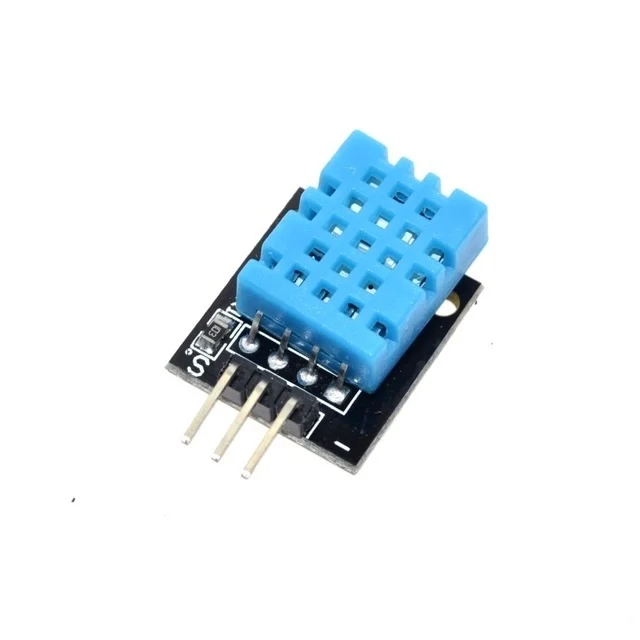
DHT11 Temperature and Humidity Sensor Module
Use this budget DHT11 sensor with your OLED to build a working weather station once you have resolved the I2C communication issue.
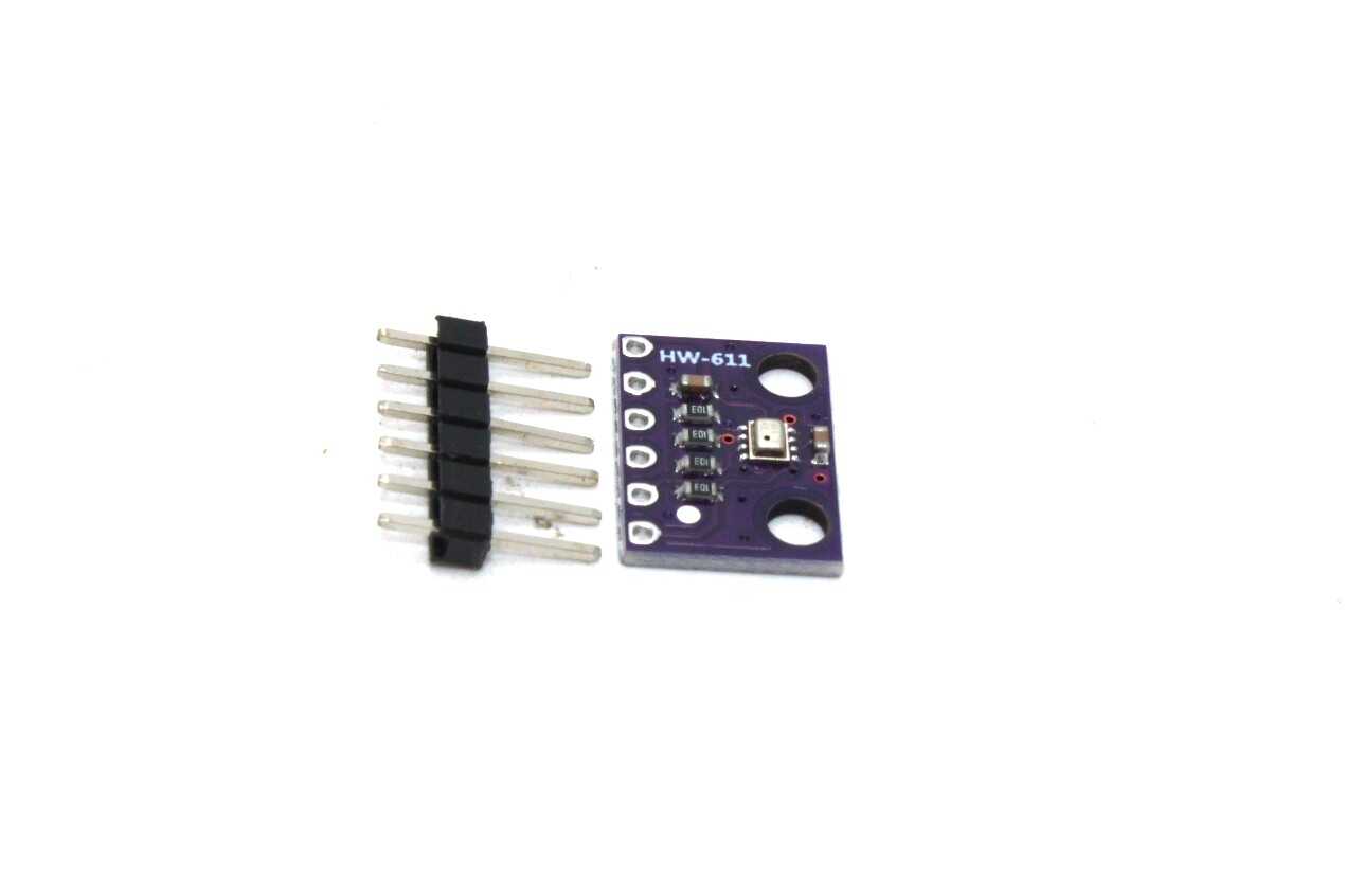
BMP280 Barometric Pressure and Altitude Sensor I2C Module
Share the same I2C bus as your OLED display — show live pressure and altitude readings once your display debug is complete.
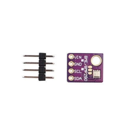
GY-BME280-5V Temperature and Humidity Sensor
5V-tolerant BME280 module — safe to run on the same I2C bus as your 5V-powered Arduino and OLED display without a level shifter.
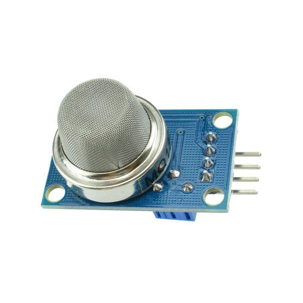
MQ-135 Air Quality / Gas Detector Sensor Module
Pair with your OLED display to build an indoor air quality monitor — a popular Arduino project that also tests your display is working correctly.
FAQ
Q1: My OLED shows only 2-3 rows of pixel noise and then goes blank — what is happening?
This usually means the library initialisation sequence is completing but with the wrong parameters. Verify the display size (128×64 vs 128×32) and the driver IC (SSD1306 vs SH1106). Also check that your power supply can handle the OLED’s current draw — OLEDs can pull 20–30mA at full brightness which can cause voltage sag on underpowered USB hubs.
Q2: The I2C scanner finds my OLED at 0x3C but the display still shows nothing in my main sketch — why?
The most common cause is the library version mismatch. Adafruit SSD1306 v1.x had a different constructor format than v2.x. Make sure your constructor matches the installed library version. The v2+ constructor is: Adafruit_SSD1306 display(WIDTH, HEIGHT, &Wire, RESET_PIN); where RESET_PIN is -1 if not connected.
Q3: After connecting a second I2C sensor, my OLED stopped working. How do I fix it?
If both devices have the same I2C address, they will conflict. Run the I2C scanner with both devices connected to see all addresses. If the sensor (e.g., BMP280 defaults to 0x76) does not conflict with the OLED (0x3C), check whether you have too many pull-up resistors on the bus lowering the effective pull-up impedance. Remove any extra 4.7kΩ resistors you added externally if both modules already have on-board pull-ups.
Q4: My OLED worked for weeks and then suddenly stopped — is it dead?
OLED panels do age and can develop dead pixels or reduced brightness over time, but complete sudden failure is more likely a loose solder joint, a cracked ribbon cable (from bending), or a cold solder joint on the VCC or SDA pin that finally gave way. Re-solder all four header pins before declaring the module dead. Also run the I2C scanner to confirm it is not just a software/library issue after a sketch update.
Q5: Can I use two OLED displays on the same Arduino?
Yes, but only if they have different I2C addresses. One OLED at 0x3C and one with the address jumper bridged to set it to 0x3D. Use both in the same sketch by initialising two separate library instances with different addresses. Alternatively, use a software I2C library (like SoftWire) to create a second I2C bus on different GPIO pins.
Need Fresh Components for Your Display Project?
If your OLED module is genuinely defective after working through this guide, it may be time for a replacement. Zbotic stocks quality display modules, sensors, and microcontroller boards with fast delivery across India.
Shop display modules and sensors at Zbotic.in — your trusted Indian electronics components store.


Add comment