
The NRF24L01 PA LNA long range 1km module is one of the most exciting upgrades you can make to your Arduino wireless projects. While the standard NRF24L01 module tops out at around 100 metres in open air, adding an external Power Amplifier (PA) and Low Noise Amplifier (LNA) pushes the reliable range to 1 kilometre and beyond under clear line-of-sight conditions. This tutorial covers everything an Indian maker needs to know — from hardware differences to library configuration and real-world tips for maximising range on a budget.
Understanding PA and LNA in RF Modules
In radio engineering, a Power Amplifier (PA) boosts the transmit signal power before it reaches the antenna, while a Low Noise Amplifier (LNA) amplifies the weak received signal with minimal added noise. In the context of the NRF24L01+PA+LNA module, both circuits are integrated onto the same board between the nRF24L01+ IC and the SMA antenna connector.
The standard NRF24L01 module uses the nRF24L01+ chip’s built-in PA, which outputs up to +7 dBm (5 mW). The PA+LNA version adds an RFX2401C or similar RF front-end chip that amplifies transmit power to approximately +20 dBm (100 mW) and improves receive sensitivity to around -95 dBm. This combination gives roughly 20 dB of link budget improvement, which translates directly to much greater range.
In India, 2.4 GHz ISM band transmit power is regulated under WPC rules. 100 mW (20 dBm) is within the permissible limit for unlicensed use when the effective isotropic radiated power (EIRP) does not exceed 1W. The NRF24L01 PA+LNA with a standard 3 dBi antenna stays comfortably within this limit.
Standard vs PA+LNA: What Changes?
| Feature | Standard NRF24L01 | NRF24L01 PA+LNA |
|---|---|---|
| TX Power | +7 dBm max | +20 dBm (~100 mW) |
| RX Sensitivity | -82 dBm @ 2 Mbps | -95 dBm |
| Antenna | Onboard PCB trace | External SMA (detachable) |
| Operating voltage | 3.3V (50 mA peak) | 3.3V (220 mA peak) |
| Indoor range | ~30 m typical | ~200 m typical |
| Open-air LOS range | ~100 m | ~1000 m (1 km) |
| Price (India) | Rs.60 to Rs.120 | Rs.200 to Rs.450 |
The key insight from the table: the PA+LNA version draws 220 mA peak during transmission, compared to the standard module’s 50 mA. This difference is the root cause of nearly all problems Indian makers encounter when first trying the PA+LNA module.
Critical Power Supply Requirements
This section can save you hours of debugging. The Arduino 3.3V pin is rated at only 50 mA on most boards (Uno, Nano, Pro Mini). Powering the NRF24L01 PA+LNA directly from the Arduino 3.3V pin WILL cause brownouts, random disconnects, and failed transmissions. The module will appear to work but then fail unpredictably.
The solution is always to power the PA+LNA module from a dedicated 3.3V regulator capable of at least 250 mA. Recommended options:
- AMS1117-3.3 LDO regulator (800 mA output) from the 5V rail — cheapest option, around Rs.5 each.
- LD1117 or LM1117-3.3 — same family, widely available at Indian electronics shops.
- NRF24L01 adapter module with built-in LDO and 100uF decoupling capacitor — plug-and-play solution for about Rs.30.
Additionally, place a 100 uF electrolytic capacitor and a 100 nF ceramic capacitor in parallel directly across the VCC and GND pins of the module. This decoupling is critical to absorb the current spikes during transmission.
Wiring NRF24L01 PA+LNA to Arduino
The pin mapping is identical to the standard NRF24L01. The only difference is that VCC must come from a stable external 3.3V source, not the Arduino’s onboard regulator.
| NRF24L01 Pin | Arduino Uno Pin | Notes |
|---|---|---|
| VCC | External 3.3V regulator | NOT Arduino 3.3V pin |
| GND | GND (shared) | Common with Arduino GND |
| CE | D9 | Chip Enable (any digital pin) |
| CSN | D10 | SPI Chip Select |
| SCK | D13 | SPI Clock |
| MOSI | D11 | SPI Data (Master Out) |
| MISO | D12 | SPI Data (Master In) |
| IRQ | Not required | Optional interrupt pin |
For the ESP32, the SPI pins are different: MOSI on GPIO23, MISO on GPIO19, SCK on GPIO18, and CE/CSN on any GPIO you choose (commonly GPIO4 and GPIO5). The ESP32’s 3.3V output can supply up to 500 mA depending on the USB power source — enough for light use, but an external regulator is still strongly recommended for reliable long-range operation.
Configuring the RF24 Library for Maximum Range
Install the TMRh20 RF24 library from the Arduino Library Manager. This is the most maintained fork and supports all nRF24L01+ features including auto-acknowledgement and dynamic payloads.
#include <SPI.h>
#include <RF24.h>

RF24 radio(9, 10); // CE, CSN

const byte address[6] = "00001";

void setup() {
  Serial.begin(9600);
  radio.begin();

  // Long range settings
  radio.setPALevel(RF24_PA_MAX);       // MAX power for PA+LNA
  radio.setDataRate(RF24_250KBPS);     // Slowest = best range
  radio.setChannel(108);               // Avoid Wi-Fi channels (1-13)
  radio.setCRCLength(RF24_CRC_16);     // Stronger error checking
  radio.enableAckPayload();            // ACK with data
  radio.setRetries(15, 15);            // Max retries: 15 delays of 4ms each

  radio.openWritingPipe(address);
  radio.openReadingPipe(1, address);
  radio.startListening();

  Serial.println("NRF24L01 PA+LNA Ready");
}

void loop() {
  if (radio.available()) {
    char text[32] = "";
    radio.read(&text, sizeof(text));
    Serial.print("Received: ");
    Serial.println(text);
  }
}
The three most impactful settings for range are:
- RF24_250KBPS data rate: The slowest rate gives the best sensitivity and longest range. Trade-off is reduced throughput (250 kbps vs 2 Mbps), but for sensor data this is irrelevant.
- RF24_PA_MAX: Sets the PA+LNA chip to maximum output power.
- Channel 108: Most Wi-Fi networks in India use channels 1, 6, and 11 (or auto-select). Channel 108 at 2.508 GHz is outside the Wi-Fi band and avoids almost all interference.
Field-Tested Tips to Hit 1km in India
Antenna Orientation Matters
The included antenna is a vertical monopole (omnidirectional in the horizontal plane). For maximum range between two fixed points, mount both antennas vertically and ensure they have a clear line of sight. Avoid pointing the antenna tip directly at the receiver, as the radiation pattern has a null directly above and below the antenna tip.
Elevation Wins
Every metre of elevation reduces ground reflections and clutter. Mounting the module on a 3-metre pole or rooftop can easily double real-world range compared to placing it at ground level. This is especially relevant for Indian agriculture projects where sensors may be in low-lying fields with vegetation blocking the path.
Avoid 2.4 GHz Congestion
Indian cities have extremely dense Wi-Fi deployments. Use the RF24 library’s scanNetworks-style channel scan (available in examples) to find a quiet channel before deploying. Channel 108 (2508 MHz) and channels 96-100 are generally clean in Indian urban environments.
Shielding and PCB Layout
Keep the NRF24L01 PA+LNA module away from Arduino clock oscillators and USB-to-serial chips, which radiate RF noise in the GHz range. A small separation of 5 cm and a ground plane between the module and the main board significantly improves sensitivity.
Common Problems and Solutions
Module Not Detected (radio.begin() returns false)
This almost always means a wiring problem or insufficient power. Check: (1) SPI connections, (2) VCC is 3.3V and stable under load, (3) all SPI lines have solid connections (PA+LNA modules can be sensitive to breadboard contact resistance). Try adding a 10 uF capacitor directly across VCC-GND on the module’s pins.
Works at Short Range, Fails at Distance
The power supply brownout issue. The module transmits fine at low power but when switching to max PA output, the current spike causes VCC to drop. Verify your 3.3V regulator can deliver 250 mA and add decoupling capacitors.
One-Way Communication Only
Both modules must be on the same channel and the same address. Check that one module calls startListening() and the other calls stopListening() before writing. The RF24 library is not symmetric in the way standard serial is.
Intermittent Data Loss at 1km
Enable auto-acknowledgement (default is on) and increase retries with setRetries(15, 15). At 250 kbps, each retry adds 4 ms delay. Consider reducing payload size to 8-16 bytes for critical data, as smaller packets have a higher probability of successful reception in marginal link conditions.
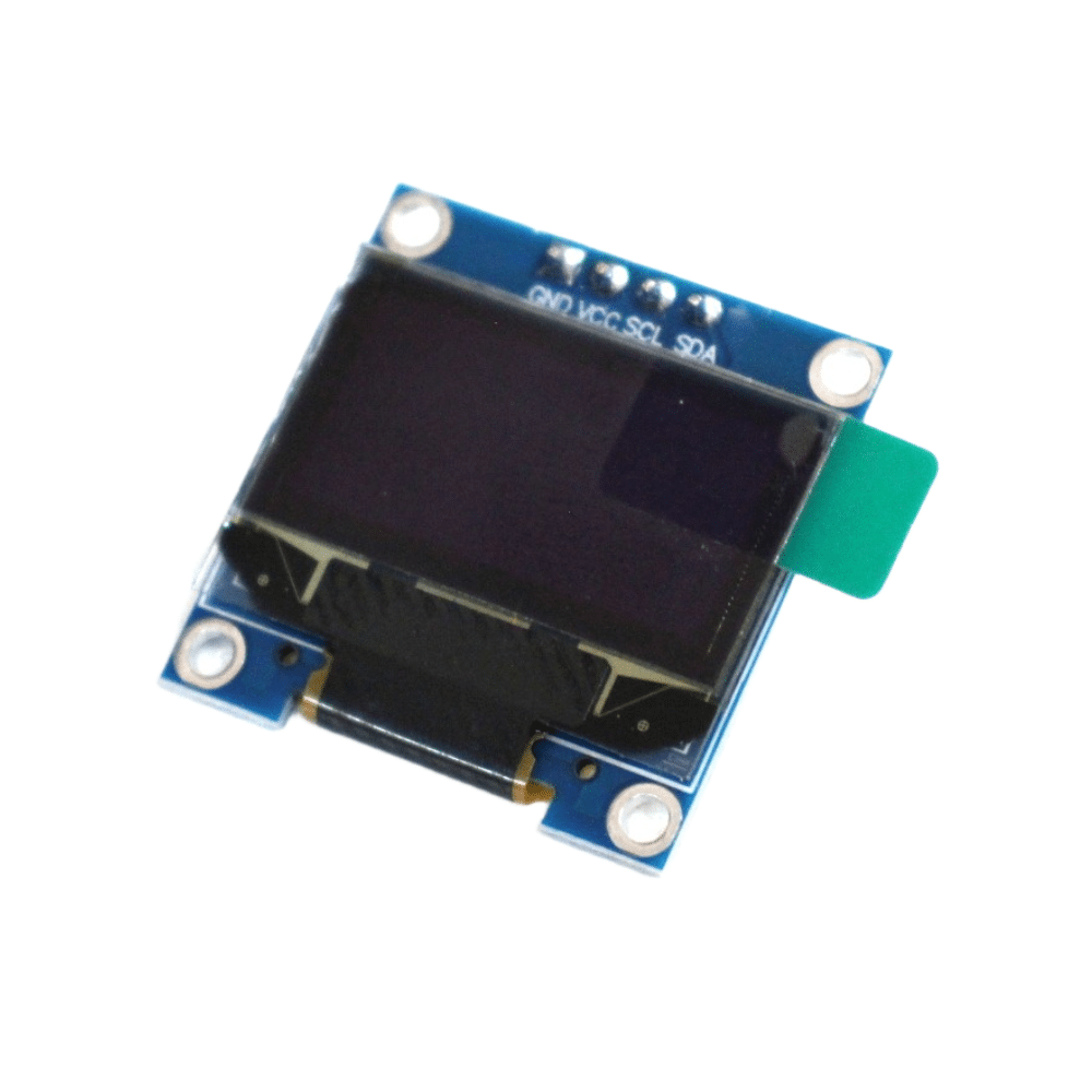
0.96 Inch I2C OLED LCD Module 4pin White SSD1306
Add a local display to your NRF24L01 base station to show received sensor data in real time. Compact, low power, and easy to integrate with the RF24 library using just 2 I2C wires.
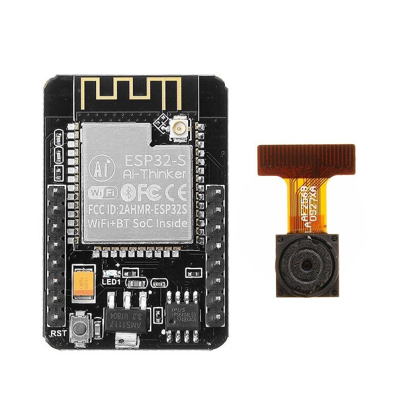
Ai Thinker ESP32 CAM Development Board WiFi+Bluetooth with Camera
Use as a cloud gateway for your NRF24L01 sensor network. Receives data from remote NRF24L01 nodes and uploads to AWS IoT, Blynk, or ThingSpeak via Wi-Fi. Includes onboard camera for visual monitoring.
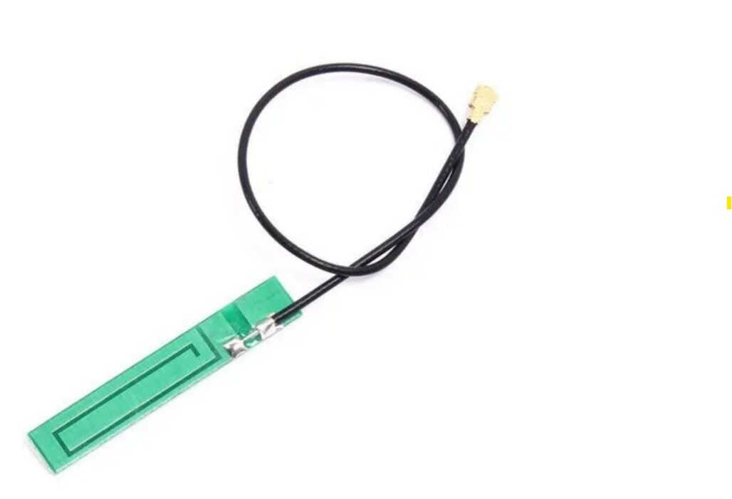
15cm 3dBi GSM/GPRS/3G PCB Antenna with IPEX Connector
Upgrade your NRF24L01 PA+LNA antenna for even better range. The IPEX connector is compatible with most PA+LNA module antenna ports. Higher gain antenna can push range well beyond 1 km in open terrain.
Frequently Asked Questions
Is the NRF24L01 PA+LNA the same as standard NRF24L01 in terms of code?
Yes, the Arduino code (RF24 library) is identical. The PA and LNA are hardware additions on the PCB that are transparent to the microcontroller. The only software change is setting setPALevel(RF24_PA_MAX) to take advantage of the higher output power.
Can I use NRF24L01 PA+LNA with a Raspberry Pi?
Yes. The RF24 library has Python and C++ versions for Linux/Raspberry Pi. The SPI interface is the same. Power supply requirements are the same — use a dedicated 3.3V regulator capable of 250 mA, not the Raspberry Pi’s onboard 3.3V rail which is shared with other components.
Why does my module work for a few seconds and then stop?
This is the classic power brownout symptom. The module starts at low power, and when it switches to full PA power for the first long-distance transmission, the voltage drops and the module resets. Add a 100 uF capacitor directly across VCC and GND on the module and use a proper external 3.3V regulator rated at 500 mA or more.
Can I use multiple NRF24L01 PA+LNA modules with one Arduino?
Yes, using different CSN pins for each module. The RF24 library supports multiple radios on the same SPI bus. Use a separate CE and CSN pin pair for each module and instantiate a separate RF24 object for each.
What is the actual 1 km range claim? Is it real?
1 km is achievable under ideal conditions: completely flat terrain, no obstructions, both antennas elevated, 250 kbps data rate, and good power supply. In Indian conditions with buildings, vegetation, and 2.4 GHz interference, expect 200 to 500 m reliably. For guaranteed multi-kilometre range, consider LoRa modules instead.
Build Your Long-Range Wireless Network Today
Zbotic carries NRF24L01 PA+LNA modules, ESP32 boards, and all the accessories you need to build a 1 km wireless sensor network. Order before 3 PM for same-day dispatch to anywhere in India.


Add comment