
If you have ever tried to make a robot move in a straight line or position a robotic arm to an exact angle, you already know how frustrating it is when motors behave unpredictably. The solution lies in motor encoders — sensors that give your microcontroller real-time feedback about shaft position, direction, and speed. This guide covers everything you need to know about quadrature encoder interfacing with Arduino, from the underlying theory to working code you can run today.
What Is a Motor Encoder?
A motor encoder is a feedback device attached to a motor shaft that converts rotational motion into electrical pulses. Each pulse represents a known fraction of one full rotation, so by counting pulses you can determine exactly how far the shaft has turned. Encoders are the backbone of closed-loop motor control systems used in CNC machines, 3D printers, robotics arms, and autonomous ground vehicles.
Without an encoder, your motor is running open-loop — you send a command and hope it reaches the target. With an encoder, you measure the actual result and correct for any error. This difference is enormous in practice. A DC gear motor running open-loop might overshoot a target position by 10–20 degrees due to inertia and load variation. The same motor with encoder feedback and a PID controller can hold position within fractions of a degree.
In the Indian maker ecosystem, encoders are most commonly used in wheeled robots (to measure distance and speed), pick-and-place arms (for joint angle tracking), motorised camera sliders, and CNC routers. They are available in resolutions from 11 PPR (pulses per revolution) on cheap gear motors up to 2048 PPR on precision industrial units.
How Quadrature Encoding Works
A standard single-channel encoder produces one pulse train — it can count rotation but cannot tell you the direction. A quadrature encoder has two output channels, conventionally called Channel A and Channel B, that produce square waves 90 degrees out of phase with each other (hence the name quadrature).
By comparing which channel leads the other, the microcontroller can determine direction:
- A leads B (A rises first): motor rotating clockwise (forward)
- B leads A (B rises first): motor rotating counter-clockwise (reverse)
Resolution is typically expressed as PPR (pulses per revolution) or CPR (counts per revolution). When you count both rising and falling edges of both channels — called X4 decoding — the effective resolution is 4x the PPR. A 100 PPR encoder yields 400 counts per revolution with X4 decoding, giving you 0.9-degree resolution per count.
Higher resolution encoders improve control accuracy but increase the interrupt load on your microcontroller. For a 500 PPR encoder at 3000 RPM, that is 500 x 4 x 50 = 100,000 interrupt events per second — well within Arduino Mega capability but tight on an Uno running other tasks simultaneously.
Types of Encoders: Optical vs Magnetic
Optical Encoders
Optical encoders use a slotted disc (code wheel) that interrupts an infrared LED-photodetector pair. As the disc rotates, light passes through slots and generates pulses. They are very accurate and immune to magnetic interference, but are sensitive to dust, moisture, and shock. They are common in laboratory equipment and high-end CNC machines.
Magnetic Encoders
Magnetic encoders use a Hall effect sensor and a magnetised disc or ring magnet. They are more robust than optical types — tolerant of dust, oil, and vibration — making them ideal for robotics and outdoor applications. Most DC gear motors with encoders sold in India (such as the 25GA-370 series) use Hall effect sensors. They are typically 11 PPR on the motor shaft, but with a gear ratio of 30:1 or higher, effective output shaft resolution can exceed 300 counts per revolution.
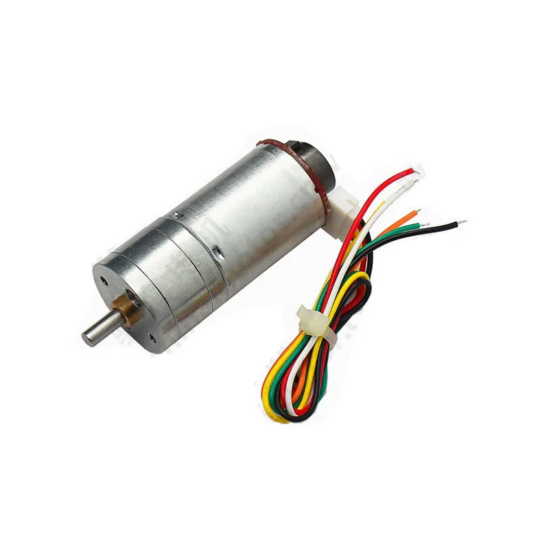
25GA-370 12V 12RPM DC Gear Motor with Encoder
A popular Hall-effect encoder gear motor for Arduino robotics. Built-in quadrature encoder gives position and direction feedback, perfect for closed-loop drive systems.
Wiring a Quadrature Encoder to Arduino
Most DC gear motors with encoders have 6 wires: 2 for the motor (M+ and M-) and 4 for the encoder (VCC, GND, Channel A, Channel B). The encoder logic runs at 3.3 V or 5 V depending on the model — always check the datasheet.
For a 5 V Hall-effect encoder on an Arduino Uno or Mega:
| Encoder Wire | Arduino Pin | Notes |
|---|---|---|
| VCC (Red) | 5V | Use encoder’s rated voltage |
| GND (Black) | GND | Common ground |
| Channel A (Yellow) | Pin 2 | Must be interrupt-capable pin |
| Channel B (Green) | Pin 3 | Must be interrupt-capable pin |
On an Arduino Uno, only pins 2 and 3 support external interrupts. The Arduino Mega has six interrupt pins (2, 3, 18, 19, 20, 21), making it better for multi-motor systems. Always add a 100 nF decoupling capacitor between the encoder VCC and GND pins to suppress noise.
Important: Keep encoder wires as short as possible and route them away from motor power cables to minimise electromagnetic interference. Twisted pair wiring for channels A and B significantly improves noise immunity at high pulse rates.
Arduino Code: Reading Encoder Pulses
The most reliable method for reading a quadrature encoder on Arduino is using hardware interrupts. Both channels must be connected to interrupt-capable pins.
// Quadrature Encoder with Arduino
// Channel A -> Pin 2 (INT0), Channel B -> Pin 3 (INT1)

#define ENC_A 2
#define ENC_B 3

volatile long encoderCount = 0;
volatile bool lastA = false;

void setup() {
  Serial.begin(115200);
  pinMode(ENC_A, INPUT_PULLUP);
  pinMode(ENC_B, INPUT_PULLUP);
  attachInterrupt(digitalPinToInterrupt(ENC_A), encoderISR, CHANGE);
  attachInterrupt(digitalPinToInterrupt(ENC_B), encoderISR, CHANGE);
}

void encoderISR() {
  bool a = digitalRead(ENC_A);
  bool b = digitalRead(ENC_B);
  if (a == b) {
    encoderCount++;  // Clockwise
  } else {
    encoderCount--;  // Counter-clockwise
  }
}

void loop() {
  static unsigned long lastPrint = 0;
  if (millis() - lastPrint >= 200) {
    lastPrint = millis();
    noInterrupts();
    long count = encoderCount;
    interrupts();
    Serial.print("Encoder Count: ");
    Serial.println(count);
  }
}
This uses the X2 decoding method (interrupts on CHANGE for both channels). The noInterrupts() and interrupts() guards are essential when reading a volatile long on an 8-bit AVR, since the read is not atomic and could be interrupted mid-read, yielding a corrupted value.
For X4 decoding (double the resolution), trigger interrupts on both RISING and FALLING edges of both channels and use a state machine to determine direction from the two-bit state transitions.
Calculating RPM and Speed
RPM can be calculated from the encoder pulse rate. Measure the number of counts in a fixed time window:
// Add to your sketch
// Assume COUNTS_PER_REV = 4 * PPR (X4 decoding) or 2 * PPR (X2)
#define COUNTS_PER_REV 44  // 11 PPR * 4 for X4 on 25GA-370

float calculateRPM() {
  static long prevCount = 0;
  static unsigned long prevTime = 0;
  unsigned long now = millis();
  unsigned long dt = now - prevTime;
  if (dt == 0) return 0;

  noInterrupts();
  long current = encoderCount;
  interrupts();

  long delta = current - prevCount;
  prevCount = current;
  prevTime = now;

  float revs = (float)delta / COUNTS_PER_REV;
  float rpm = (revs / dt) * 60000.0f;
  return rpm;
}
To convert RPM to linear speed for a wheeled robot, multiply by wheel circumference: speed (m/s) = (RPM / 60) * wheel_circumference. For a 65 mm diameter wheel that is approximately (RPM / 60) * 0.204 m/s.
Position Tracking and Direction Detection
Position tracking uses the cumulative encoder count. Define a zero point at startup or after a homing sequence, then track counts from that reference:
- Degrees: angle = (encoderCount / COUNTS_PER_REV) * 360.0
- Distance (wheels): dist_mm = (encoderCount / COUNTS_PER_REV) * wheel_circumference_mm
- Linear (leadscrew): dist_mm = (encoderCount / COUNTS_PER_REV) * lead_mm
Direction is implicit in the sign of the count. Positive counts indicate clockwise rotation (as wired), negative counts indicate counter-clockwise. If direction appears reversed, simply swap the Channel A and Channel B wires, or negate the count in the ISR.
Combining Encoder with PID Control
An encoder alone is a sensor. Its real value is unlocked when used inside a closed-loop controller. The most common approach is a PID (Proportional-Integral-Derivative) controller:
- Set a target position (desired encoder count)
- Read current position from encoder
- Calculate error = target minus current
- PID output = Kp x error + Ki x integral(error) + Kd x d(error)/dt
- Apply output as PWM duty cycle to motor driver
- Repeat at a fixed interval (typically 10-50 ms)
For a detailed PID implementation, the Arduino PID library by Brett Beauregard is well-documented and widely used. Start with Ki=0 and Kd=0, tune Kp until the system responds quickly without oscillation, then add Ki to eliminate steady-state error, and Kd to reduce overshoot.
A motor with encoder is the ideal platform for learning PID tuning. You can see the effect of each gain immediately by monitoring encoder count in the Serial Plotter.
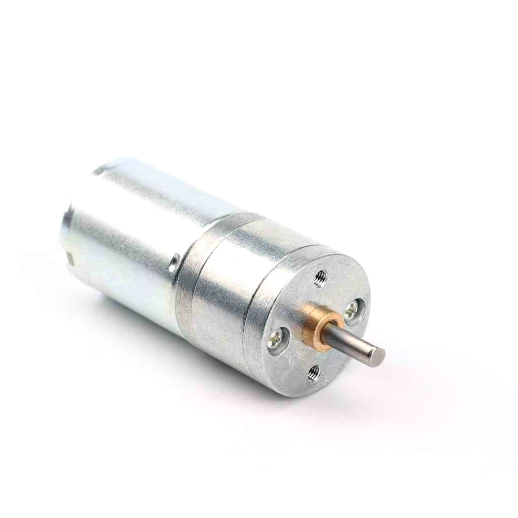
25GA-370 12V 12RPM DC Reducer Gear Motor
High-torque gear motor for robotics. Pair with the encoder version above to build a PID-controlled position or velocity loop without external sensors.
Common Issues and Fixes
Encoder count drifts even when motor is stopped
Usually caused by electrical noise on the encoder lines, especially when the motor driver is on the same power rail. Add 100 nF ceramic capacitors from each channel line to GND, use separate power supplies for logic and motors, and add a common-mode choke to the encoder cable if possible.
Count increments unpredictably in one direction
This is the classic bounce issue from contact-type encoders or noisy Hall sensors. Use hardware debouncing (RC filter: 1 kOhm + 100 nF on each channel) or software debouncing with a short dead-time in the ISR. Most Hall encoders do not need this, but cheap optical discs often do.
Missed counts at high speed
If the motor spins fast enough that pulse widths become shorter than the Arduino’s interrupt response time (approximately 3-4 microseconds), you will miss counts. Reduce encoder resolution, use a faster microcontroller (ESP32’s PCNT peripheral handles this natively), or add a dedicated encoder chip like the LS7366R.
Direction detection is wrong
Swap Channel A and Channel B wires, or reverse the polarity of the motor wires while keeping the encoder wires the same — this reverses mechanical direction without changing the encoder wiring logic.
Project Ideas for India Makers
- Line-following robot with odometry: Two encoder motors plus L298N driver gives you both path following and dead-reckoning navigation.
- Motorised pan-tilt camera head: Encoder on each axis allows return-to-position and time-lapse automation.
- CNC foam cutter: High-PPR encoders on each axis ensure accurate cuts even with load variation.
- Smart irrigation valve: Gear motor plus encoder controls valve position precisely from 0-100% open based on soil moisture sensor data.
- Balancing robot: Encoders provide wheel velocity feedback to the balance PID loop, complementing the IMU data.

25GA-370 12V 1360RPM DC Reducer Gear Motor
Higher RPM variant for speed-critical applications like belt-driven CNC stages where velocity feedback is more important than high torque.
Frequently Asked Questions
Can I use a single-channel encoder with Arduino?
Yes, but you lose direction information. A single-channel encoder is fine for speed measurement applications where direction is determined externally (e.g., from the motor command signal). For position control, always use a quadrature (two-channel) encoder.
What is the maximum encoder speed an Arduino Uno can handle?
Arduino Uno can reliably handle roughly 30,000-50,000 interrupts per second in simple ISRs. This translates to about 1500 RPM with a 100 PPR encoder using X4 decoding. For higher speeds, use an Arduino Mega (faster clock, same MCU), an ESP32, or a dedicated encoder counter IC.
Do I need pull-up resistors on encoder channels?
Hall effect encoders with push-pull outputs do not need external pull-ups. Open-collector encoders (common in optical types) require 4.7 kOhm pull-up resistors on each channel. The code above uses INPUT_PULLUP which enables Arduino’s internal 20-50 kOhm pull-ups, suitable for low-speed open-collector encoders.
Can I use the same code with an ESP32?
Yes, but ESP32 has a dedicated PCNT (Pulse Counter) peripheral that handles quadrature decoding in hardware, freeing up the main CPU. Use the ESP32Encoder library for best results. The PCNT peripheral supports X1, X2, and X4 decoding and handles speeds that would overwhelm Arduino ISRs.
My motor has 11 PPR — is that enough for position control?
On the motor shaft, 11 PPR (44 counts/rev with X4) seems low. But with a 30:1 gear ratio, the output shaft resolution becomes 44×30 = 1320 counts/rev, equivalent to 0.27 degree per count — more than enough for most robotics applications. Always account for gear ratio when evaluating encoder resolution.
Where can I buy encoder motors in India?
Zbotic.in stocks the 25GA-370 DC gear motor with Hall-effect encoder, compatible with standard motor drivers and suitable for 5 V or 12 V systems. Shipping is available across India with fast dispatch from their warehouse.
Explore our full range of DC gear motors, encoder motors, and motor drivers at Zbotic Motors & Actuators. Fast shipping across India, GST invoice on all orders.


Add comment