
LM317 Voltage Regulator: Adjustable Power Supply Circuit Guide
The LM317 voltage regulator adjustable IC is one of the most popular and versatile components in every electronics hobbyist’s toolkit. Whether you are powering an Arduino, charging a battery, or testing a sensor module, the LM317 lets you dial in exactly the output voltage you need — from 1.25V all the way up to 37V — with just two resistors. In this comprehensive guide, we’ll cover everything from the basic circuit theory to practical DIY power supply builds suited for the Indian maker community.
What Is the LM317 Voltage Regulator?
The LM317 is a three-terminal positive adjustable linear voltage regulator, originally designed by National Semiconductor (now Texas Instruments). It has been a staple component in electronics for over four decades, and for good reason — it is cheap, robust, easy to use, and widely available in Indian component markets.
Unlike fixed-voltage regulators such as the 7805 (5V) or 7812 (12V), the LM317 allows you to set any output voltage between 1.25V and 37V using an external resistor divider. This makes it far more flexible for DIY power supply designs where you need a specific voltage that doesn’t match standard fixed-regulator values.
The IC is available in several packages in India — the most common being the TO-220 (suitable for through-hole breadboard prototyping and PCB use) and the TO-3 metal can (for high-current applications). You can pick one up at virtually any electronics supplier in Nehru Place, SP Road Bengaluru, or from online stores like Zbotic for a few rupees.
Key application areas include:
- Variable bench power supplies for labs and workshops
- Battery charging circuits (NiMH, SLA, custom lithium packs)
- Constant-current LED drivers
- Powering sensor modules and microcontrollers at non-standard voltages (e.g., 3.3V, 9V)
- Motor speed control via adjustable voltage
Pinout and Key Specifications
The LM317 in a TO-220 package has three pins:
- Pin 1 — ADJ (Adjust): Connected to the resistor divider that sets the output voltage.
- Pin 2 — OUTPUT (Vout): The regulated output voltage comes from this pin.
- Pin 3 — INPUT (Vin): The unregulated input supply connects here.
Important note: On the TO-220 package, pin 2 (OUTPUT) is the centre pin, which is different from many other regulators. Always verify the datasheet before soldering.
Key electrical specifications of the LM317:
- Output Voltage Range: 1.25V to 37V (adjustable)
- Maximum Input Voltage: 40V
- Minimum Input-to-Output Differential (Dropout): ~3V
- Maximum Output Current: 1.5A (with proper heatsink)
- Internal Reference Voltage (Vref): 1.25V
- Typical Load Regulation: 0.1%
- Typical Line Regulation: 0.01% per volt
- Built-in current limiting, thermal shutdown, and safe area protection
The 3V dropout voltage is important to remember — if you want 12V output, your input supply must be at least 15V. For a 5V output from a 9V battery, you are right at the edge (9V − 5V = 4V dropout margin), which is acceptable.
Output Voltage Formula and Resistor Selection
This is where the LM317’s magic happens. The output voltage is determined by just two resistors (R1 and R2) connected as a voltage divider from the output pin to the ADJ pin to GND.
The formula is:
Vout = 1.25 × (1 + R2/R1) + Iadj × R2
In practice, the adjust pin current (Iadj) is very small (typically 50–100 µA), so it is often ignored, simplifying to:
Vout ≈ 1.25 × (1 + R2/R1)
The standard value for R1 is 240Ω (or 220Ω is acceptable). The LM317 maintains exactly 1.25V between its output and ADJ pins, so R1 always carries 1.25/240 = ~5.2mA, which keeps the regulation stable regardless of load.
Common resistor values for popular output voltages (R1 = 240Ω):
| Target Vout | R2 Value | Nearest Standard |
|---|---|---|
| 3.3V | 393Ω | 390Ω |
| 5V | 720Ω | 720Ω (680+47) |
| 9V | 1488Ω | 1.5kΩ |
| 12V | 2064Ω | 2.1kΩ (2k+100) |
| 15V | 2640Ω | 2.7kΩ |
For a fully adjustable power supply, replace R2 with a 5kΩ potentiometer in series with a 240Ω fixed resistor (to prevent the output from ever going below 1.25V). This gives you a continuously adjustable output from 1.25V to about 26V with a 30V input.
Basic Adjustable Power Supply Circuit
Here is the standard LM317 adjustable power supply circuit that you can build on a breadboard in under 10 minutes:
Components required:
- LM317T (TO-220 package) — 1 piece
- Input capacitor: 0.1µF ceramic or 0.33µF film
- Output capacitor: 1µF electrolytic (optional but recommended)
- R1 = 240Ω resistor (1/4W)
- R2 = 5kΩ potentiometer + 240Ω fixed resistor in series (for adjustable output)
- Protection diode D1: 1N4001 from output to input (protects against reverse voltage during capacitor discharge)
- Protection diode D2: 1N4001 from output to ADJ (protects during capacitor discharge through ADJ pin)
- Heatsink for LM317 (TO-220 clip-on type, or use thermal paste on a metal enclosure)
Circuit connections:
- Connect your DC input (from a transformer+bridge rectifier or a wall adapter) to the INPUT pin (pin 3) of LM317 with the input capacitor to GND.
- Connect R1 (240Ω) between the OUTPUT pin (pin 2) and the ADJ pin (pin 1).
- Connect the potentiometer (R2, wiper and one end) between the ADJ pin and GND. The 240Ω fixed resistor goes in series between ADJ and the pot to set a minimum voltage.
- Connect the output capacitor between OUTPUT and GND.
- Add D1 from OUTPUT to INPUT and D2 from OUTPUT to ADJ for protection.
- Your regulated variable output is available at pin 2 and GND.
Heat dissipation note: The LM317 dissipates heat equal to (Vin − Vout) × Iload. If you’re dropping 10V at 1A, that’s 10W — you will absolutely need a heatsink. Use thermal paste and a TO-220 heatsink rated for at least 15W. Without a heatsink, the internal thermal shutdown will trigger above about 125°C junction temperature.
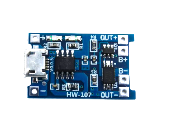
TP4056 1A Li-Ion Battery Charging Board Micro USB with Current Protection
A ready-made Li-ion charging solution using a dedicated CC/CV IC. Ideal companion to LM317 circuits for building custom chargers with overcurrent and overcharge protection built-in.
Boosting Output Current Beyond 1.5A
The LM317’s maximum output current is 1.5A, which is sufficient for most bench supply tasks and microcontroller projects. However, if you need more current — say, for motor drivers, high-power LED arrays, or SLA battery chargers — there are two common techniques.
Method 1: External Pass Transistor
Add a PNP power transistor (e.g., 2N3055, TIP35C, BD140) as a pass element. The LM317 controls the base of the transistor, and the bulk of the current flows through the transistor’s collector-emitter path. This configuration can handle 5A–20A depending on the transistor chosen. Remember to heatsink both the transistor and the LM317 adequately.
Method 2: Parallel LM317 ICs
Two LM317 ICs can be paralleled by adding a small ballast resistor (0.1Ω, 5W) in series with each IC’s output. This balances the load sharing and effectively doubles the current capacity to 3A. This method is simpler but wastes some power across the ballast resistors.
For most Indian hobbyist applications — powering Raspberry Pi, Arduino, ESP32 projects, or small motors — the standard 1.5A LM317 circuit is more than adequate.
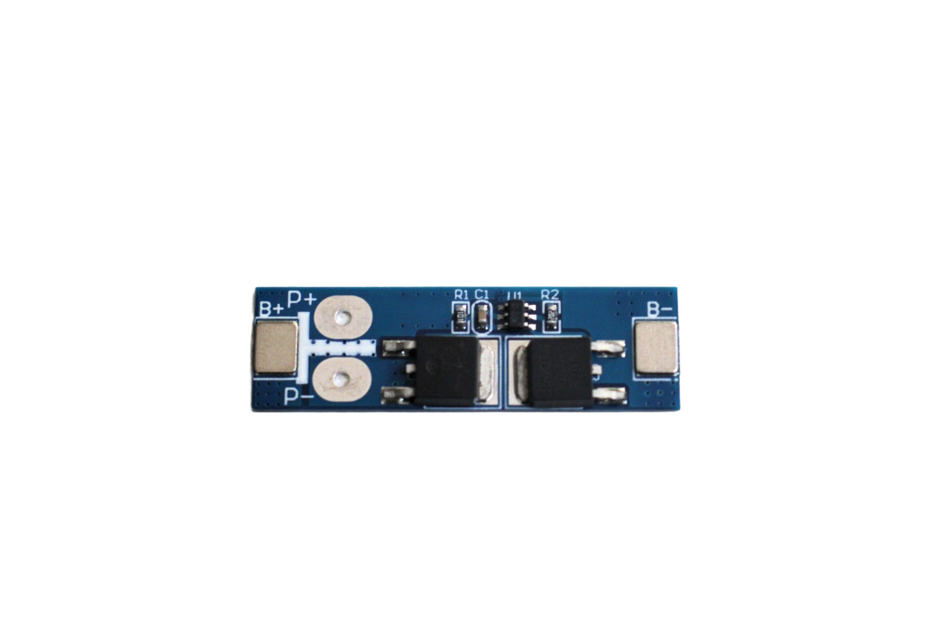
1S 12A 3.6V BMS Battery Protection Board for Li-ion Cell
Add proper BMS protection to your single-cell Li-ion based power supply projects. Prevents overcharge, over-discharge, and short circuit at up to 12A current — essential for any LM317-based charger build.
Protection Features and Safe Operation
One reason the LM317 has remained so popular is its built-in protection features that make it hard to destroy even during prototype-stage accidents:
Thermal Shutdown: The IC monitors its own junction temperature. When it exceeds 150°C, it cuts off the output. This protects against heatsink failure or insufficient thermal design. The supply resumes automatically once the temperature drops — but repeated thermal cycling will eventually degrade the IC, so treat thermal shutdown as a warning sign to improve your heatsink.
Current Limiting: The LM317 limits output current to approximately 1.5A–2.2A (depending on the grade). If you short the output terminals, the IC survives (unlike a bare transistor stage). However, sustained short-circuit will engage the thermal shutdown.
Safe Operating Area (SOA) Protection: At higher voltages, the LM317 reduces its current limit proportionally to prevent transistor breakdown. This means at 40V input with 1.25V output, you might only get 200–300mA safely, not the full 1.5A.
Best practices for Indian hobbyists:
- Always use a heatsink. Indian summers (40°C+ ambient) significantly reduce thermal headroom.
- Use a fuse on the input side (1A fast-blow for a 1A design).
- Keep input capacitor close to the IC’s input pin to suppress oscillations.
- Avoid inputs above 35V to maintain a margin below the 40V absolute maximum.
- Use 1% tolerance metal film resistors for R1 and R2 to maintain accurate output voltage.
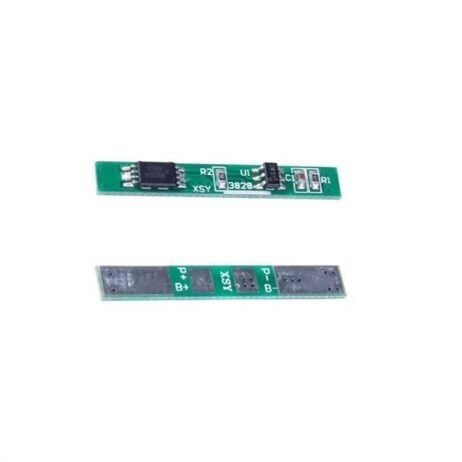
1S 3.7V 2A 1MOS BMS Li-ion 18650 Battery Protection Board
Compact 1S BMS board for single 18650 cells. Use alongside LM317 circuits when building portable regulated power banks or backup power supplies for field projects.
Practical DIY Projects for Indian Makers
Here are four real-world projects you can build with an LM317 right now:
1. Variable Bench Power Supply (1.25V–25V, 1A)
Use a 24V centre-tapped transformer, a bridge rectifier (4 × 1N4007), a 2200µF filter capacitor, and the standard LM317 adjustable circuit with a 5kΩ pot. Add a voltmeter module and ammeter module for a complete bench supply. Total cost in India: approximately ₹300–₹500 from local component markets.
2. NiMH Battery Charger (Constant Current)
When R2 is replaced with a sense resistor and the ADJ pin controls only current (not voltage), the LM317 acts as a constant-current source. Set Iout = 1.25/Rsense. For a 500mA NiMH charger, use Rsense = 2.5Ω (2W). Add a timer circuit to cut off after the required charge time for safety.
3. 3.3V Regulator for ESP8266/ESP32 from 9V Supply
Set R1 = 240Ω, R2 = 390Ω for approximately 3.33V output. The 9V to 3.3V drop at 500mA = 2.85W, so a small heatsink is needed. This is useful when running ESP8266 projects from a 9V wall adapter without needing a separate LDO module.
4. Adjustable LED Driver (Constant Current)
Configure LM317 as a constant-current source to drive high-power LEDs. Connect R1 (sense resistor) between OUTPUT and ADJ. ADJ connects to the LED anode. Calculate Rsense = 1.25/Iled. For a 350mA LED: Rsense = 3.6Ω. Multiple LEDs can be connected in series from the output.
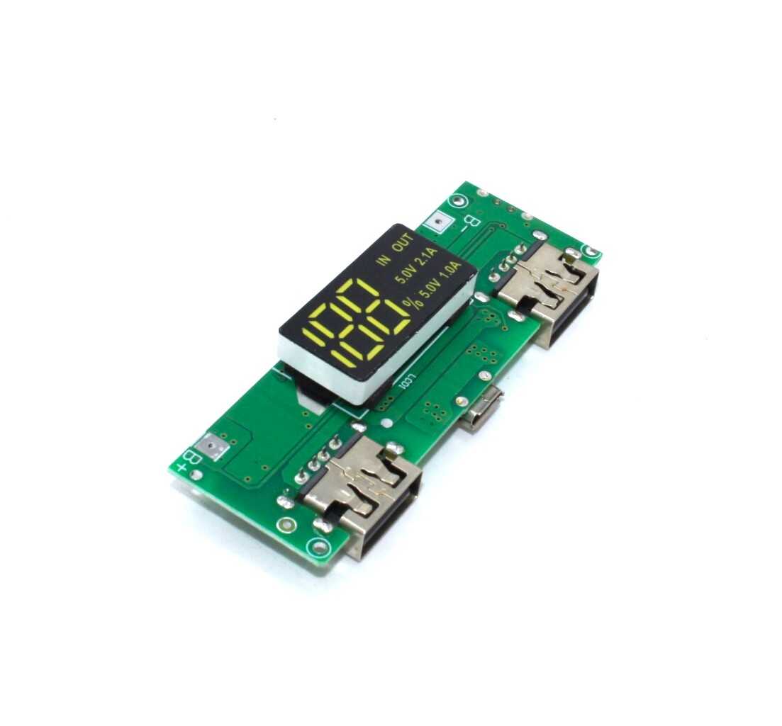
18650 5V 1A/2A Lithium Battery Digital Display & Charging Module, Dual USB Output
An all-in-one 18650 charging and boost module with dual USB output and digital display. Great companion for portable regulated power supply builds alongside your LM317 circuits.

1S 18650 Li-ion Lithium Battery BMS Charger Protection Board for 3.7V Battery
Complete protection board for 3.7V 18650 cells covering overcharge, over-discharge, and short circuit scenarios. Essential safety layer for any DIY battery pack or portable LM317-powered supply.
Frequently Asked Questions
Q1: Can the LM317 regulate below 1.25V?
No. The LM317’s internal reference voltage is 1.25V, which is the minimum achievable output. If you need a lower output (e.g., 0.8V for some FPGA cores), you will need a different IC like the LT1083 with an offset, or a proper adjustable LDO (e.g., MCP1700 series).
Q2: How do I calculate the heatsink required for LM317?
Power dissipated = (Vin − Vout) × Iload. For example, 15V in, 5V out, 1A load = 10W. The LM317 in TO-220 has a thermal resistance of 5°C/W junction-to-case. With a 2°C/W heatsink and 40°C ambient, junction temperature = 40 + 10 × (5+2) = 110°C — within the 125°C limit. Always calculate before assembling, especially in Indian summers.
Q3: Can I use the LM317 with a 9V PP3 battery as input?
Yes, but with limitations. A fresh alkaline 9V battery can source about 150–200mA continuously before its voltage sags significantly. The LM317 minimum dropout of 3V means you can regulate down to 6V max from 9V. For light loads (microcontroller projects), this works fine. For loads above 200mA, the battery will drain very quickly.
Q4: What is the difference between LM317T and LM317HV?
The standard LM317 is rated up to 40V input. The LM317HV (High Voltage) variant is rated up to 57V input, useful for higher-voltage supplies. Both use the same 1.25V reference and the same resistor formula. In India, the standard LM317T is what you will find at most component shops; the HV variant may need to be ordered online.
Q5: Why is my LM317 output voltage drifting?
Common causes: (a) Carbon-film potentiometer with poor contact quality — switch to a cermet or wire-wound pot. (b) Output capacitor too small or absent — add a 10µF electrolytic on the output. (c) Input supply with high ripple — add more filter capacitance on the input. (d) Thermal drift — the output changes slightly with temperature, normal for linear regulators.
Build Your Next Power Supply Project with Zbotic
Zbotic stocks a wide range of power components, battery modules, BMS boards, and charging ICs to help you build reliable DIY power supplies and battery management systems. Whether you need TP4056 charging modules, 18650 holders, or BMS protection boards, we have you covered with fast shipping across India.


Add comment