
Every time you connect an LED to a power supply, you need a current limiting resistor. Skip it, and the LED will draw far more current than it is designed for, overheat, and burn out within seconds — sometimes dramatically. Get it right, and your LED will glow brightly and last for thousands of hours.
This guide covers everything you need to know about LED forward voltage, LED current limiting resistors, and how to calculate the correct value for any situation — whether you are using a standard 5mm through-hole LED, a high-power SMD LED, or a 12V LED strip.
Why Does an LED Need a Current Limiting Resistor?
An LED (Light Emitting Diode) is a diode — a semiconductor device with a very non-linear relationship between voltage and current. Unlike a resistor, which limits current proportionally to voltage (Ohm’s Law), a diode barely conducts at all below its forward voltage, then conducts almost without limit once that threshold is exceeded.
This exponential I-V characteristic means that a small increase in voltage above the forward voltage causes a massive increase in current. Without a resistor to limit this, the current surges until the LED either burns out or the supply voltage drops (if the supply is current-limited). The resistor converts the excess supply voltage into heat, leaving the LED with the correct current flowing through it.
Think of the resistor as a pressure regulator for the current: the supply voltage might be 5V, the LED needs 2V across it and 20mA through it — the resistor takes the remaining 3V and limits current to exactly 20mA.
What Is LED Forward Voltage?
The forward voltage (Vf) is the voltage that drops across an LED when it is conducting at its rated current. It is a fixed electrical characteristic of the LED’s semiconductor material — it does not depend on the supply voltage. The remaining supply voltage drops across the series resistor.
Forward voltage varies by colour because different LED colours use different semiconductor materials (GaAs, GaP, GaN, InGaN) that have different bandgap energies. Higher energy photons (blue, violet) require more voltage to produce; lower energy photons (red, infrared) require less.
LED Forward Voltage by Colour
| LED Colour | Forward Voltage (Vf) | Typical Current (If) |
|---|---|---|
| Infrared (IR) | 1.2 – 1.7V | 20 – 100mA |
| Red | 1.8 – 2.2V | 10 – 30mA |
| Orange | 1.9 – 2.2V | 10 – 30mA |
| Yellow | 1.9 – 2.2V | 10 – 30mA |
| Green (standard) | 2.0 – 2.5V | 10 – 30mA |
| Blue | 3.0 – 3.5V | 10 – 30mA |
| White | 3.0 – 3.5V | 10 – 30mA |
| UV (violet) | 3.2 – 3.8V | 10 – 20mA |
Note: These are typical ranges. Always check the datasheet for your specific LED if precision matters.
The Current Limiting Resistor Formula
The formula comes directly from Ohm’s Law applied to the voltage across the resistor:
R = (Vsupply − Vf) / If
Where:
- R = Required resistance in Ohms (Ω)
- Vsupply = Supply voltage (e.g., 3.3V, 5V, 9V, 12V)
- Vf = LED forward voltage (from table above or datasheet)
- If = Desired LED current in Amperes (e.g., 0.02A for 20mA)
After calculating, choose the nearest higher standard resistor value. Running the LED at slightly less than maximum current is fine and actually extends LED life. Standard resistor values in the E12 series: 10, 12, 15, 18, 22, 27, 33, 39, 47, 56, 68, 82 (and their multiples of 10).
Worked Examples for Common Scenarios
Example 1: Red LED from Arduino 5V pin
Vsupply = 5V, Vf = 2.0V (red), If = 20mA = 0.02A
R = (5 − 2.0) / 0.02 = 3.0 / 0.02 = 150Ω
Nearest standard value ≥ 150Ω: use 150Ω or 220Ω. With 220Ω, current = 3.0 / 220 = 13.6mA — perfectly fine brightness, longer life.
Example 2: Blue LED from 3.3V ESP32 pin
Vsupply = 3.3V, Vf = 3.2V (blue), If = 10mA = 0.01A
R = (3.3 − 3.2) / 0.01 = 0.1 / 0.01 = 10Ω
Only 0.1V headroom! This is a tricky situation — the forward voltage is very close to the supply. Using a 33Ω resistor, current = 0.1 / 33 = 3mA, which is dim but safe. For reliable blue LED operation from 3.3V, it is better to use a 5V supply or choose a blue LED with Vf ≤ 3.0V.
Example 3: White LED from 9V battery
Vsupply = 9V, Vf = 3.2V (white), If = 20mA = 0.02A
R = (9 − 3.2) / 0.02 = 5.8 / 0.02 = 290Ω
Nearest standard ≥ 290Ω: use 330Ω. Current = 5.8 / 330 = 17.6mA — bright and safe.
Example 4: Infrared LED for TV Remote Emitter
Vsupply = 5V, Vf = 1.5V (IR), If = 50mA = 0.05A (IR LEDs can handle higher peak currents)
R = (5 − 1.5) / 0.05 = 3.5 / 0.05 = 70Ω
Use 68Ω (nearest E12 standard). Power: P = I² × R = 0.05² × 68 = 0.17W — safely within a 0.25W resistor rating.
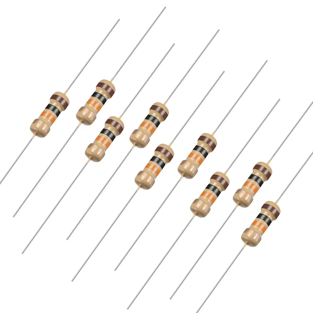
10 Ohm 0.25W Carbon Film Resistors (Pack of 50)
Essential for LED current limiting and prototyping — stock up on these reliable 0.25W carbon film resistors to have the right value ready for every project.
Multiple LEDs: Series vs Parallel Configurations
LEDs in Series
When you connect multiple LEDs in series (anode-to-cathode chain), the same current flows through all of them, but the forward voltages add up. Use one resistor for the entire chain:
R = (Vsupply − (Vf1 + Vf2 + … + Vfn)) / If
Example: 3 red LEDs (Vf = 2V each) in series from 12V, at 20mA:
R = (12 − 6) / 0.02 = 6 / 0.02 = 300Ω (use 330Ω)
Advantage of series: One resistor, all LEDs at identical current, consistent brightness. Disadvantage: If one LED fails open-circuit, all LEDs in the chain go out.
LEDs in Parallel
Connecting LEDs in parallel is generally discouraged without individual resistors for each LED. Even LEDs from the same batch have slightly different forward voltages, so one LED will always have a slightly lower Vf and will hog more current than the others. Give each parallel LED its own current limiting resistor.
With individual resistors, the total current drawn from the supply is the sum of all LED currents: Itotal = n × If.
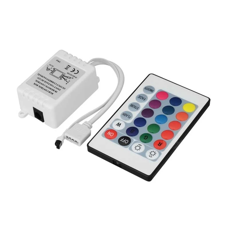
12V 5050 RGB LED Strip Controller with 24-Key IR Remote
Control your LED strip with ease — this complete controller box with IR remote handles RGB dimming and colour changes, with built-in current management for 12V 5050 strips.
LED Strips: Do They Need External Resistors?
Standard 12V 5050 SMD LED strips (like the popular cold white or RGB strips) already have current limiting resistors built into the strip itself. Every group of 3 LEDs in series has one resistor on the strip PCB. This means you do not need an external resistor when connecting the strip to a 12V supply — just connect directly to 12V+ and GND.
However, if you cut the strip to a non-standard length and accidentally cut in the middle of a 3-LED group (not at the cut marks), you may remove the resistor from the circuit, causing the remaining LEDs in that group to overdrive and burn out.
Always cut LED strips at the marked cut points — usually every 3 LEDs (approximately 5cm apart for standard strips).
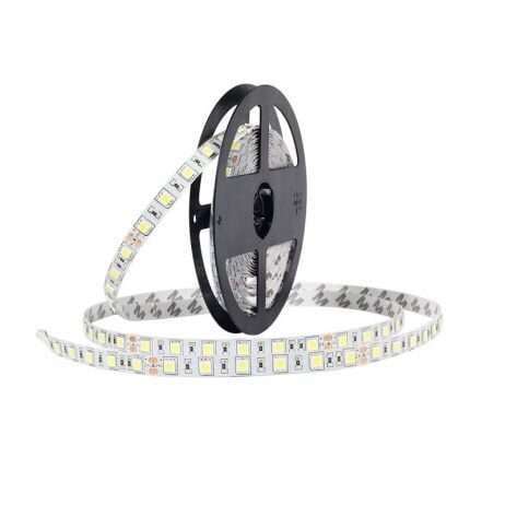
12V Cold White 5050 SMD LED Strip – 5 Meter
This 5-metre cold white LED strip has built-in current limiting resistors — just connect to 12V and it glows, no external resistor needed. Perfect for home and project lighting.
Choosing the Right Resistor Power Rating
Every resistor must be rated for the power it will dissipate. The power in the resistor is:
P = (Vsupply − Vf) × If or equivalently P = If² × R
Example: Red LED at 20mA from 5V (R = 150Ω):
P = (5 − 2.0) × 0.02 = 3 × 0.02 = 0.06W
A standard 0.25W carbon film resistor has 4× headroom — perfectly fine.
Example: LED at 100mA from 12V (high-brightness LED, R = 68Ω, Vf = 3.5V):
P = (12 − 3.5) × 0.1 = 8.5 × 0.1 = 0.85W
A 0.25W resistor would burn out. Use a 1W or 2W rated resistor for this application.
Adjusting Brightness: Running LEDs Below Max Current
You do not always need to run an LED at its maximum rated current. LEDs are generally dimmer but still visible at much lower currents:
- At 2mA, a standard LED is still visible in subdued lighting — great for indicator lights in power-saving applications
- At 5mA, you get roughly 30-40% of full brightness
- At 10mA, you get about 70% brightness with only 50% of the heat and wear
- At 20mA (full rated current), maximum brightness
For PWM brightness control (dimming with Arduino or ESP32), run the LED at its full current through the resistor and vary the duty cycle with a digital output pin. This gives more linear-appearing brightness control than reducing DC current, because the human eye perceives PWM dimming more linearly than voltage/current dimming.
Common LED Circuit Mistakes
1. Connecting an LED Directly to a Battery or Supply
The number one beginner mistake. Without a resistor, the LED may glow briefly at blinding brightness before burning out. Even with a 9V battery, always use a resistor.
2. Wrong LED Polarity
The LED simply will not light and no damage occurs (for reverse voltages below the breakdown voltage). Check that the longer lead (anode) connects to the positive supply side, and the shorter lead (cathode) toward GND.
3. Using the Same Resistor for a Different Colour LED
If you calculated a 220Ω resistor for a red LED (Vf = 2V) and swap in a blue LED (Vf = 3.2V), the current changes: I = (5 − 3.2) / 220 = 8.2mA instead of 13.6mA. The blue LED will be dimmer. Recalculate for each LED colour.
4. Forgetting That High-Power LEDs Need Heatsinking
1W and 3W power LEDs cannot be driven from a simple resistor alone — they need a constant-current driver IC and a metal heatsink. At 1W, the LED junction temperature rises fast enough to permanently degrade the diode without proper thermal management.
5. Connecting Multiple LEDs in Parallel Without Individual Resistors
As described above, one LED always wins the current battle due to Vf variation. Always give each parallel LED its own resistor.
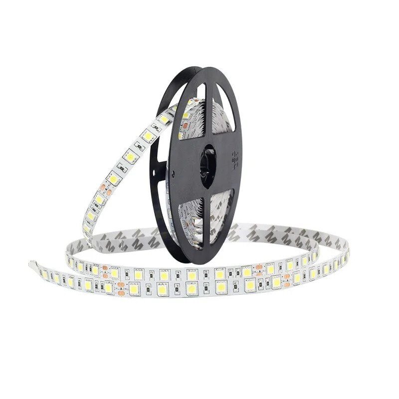
12V RGB 5050 SMD LED Strip – 5 Meter
A full-colour RGB LED strip with built-in current-limiting resistors on every segment — connect to 12V and control with a MOSFET driver or LED controller for vivid lighting effects.
Frequently Asked Questions
What happens if I don’t use a current limiting resistor with an LED?
Without a current limiting resistor, the LED will draw as much current as the source can provide. The LED may briefly glow very brightly before the excess current destroys the semiconductor junction — usually within a few seconds. The result is a dead LED, and if the current was high enough, the supply could also be damaged. Always use a resistor sized for the supply voltage, LED forward voltage, and desired current.
Can I use any resistor value as a current limiter for an LED?
You should calculate the correct value using R = (Vsupply − Vf) / If. Using too small a resistor allows too much current and burns the LED. Using too large a resistor reduces brightness — sometimes to invisibility. A range of 10 to 100 ohms above the calculated value is generally acceptable; the LED will be slightly dimmer but will last longer.
Does the resistor go before or after the LED?
It does not matter electrically — the same current flows through both components in series regardless of order. However, convention is to place the resistor on the positive (anode) side of the LED: from supply → resistor → LED anode → LED cathode → GND. Either arrangement works correctly.
What is the forward voltage of a standard red LED?
A standard through-hole red LED (5mm or 3mm) typically has a forward voltage of 1.8V to 2.2V, with 2.0V being the most commonly used figure for calculations. Blue and white LEDs have higher forward voltages of 3.0–3.5V due to their different semiconductor materials (InGaN). Always use the datasheet value if available; use the typical values from the colour table if no datasheet is available.
How do I control LED brightness with Arduino?
Use PWM (Pulse Width Modulation) via the analogWrite() function on a PWM-capable Arduino pin. The LED still gets full current when on, but the duty cycle (fraction of time it is on) varies — 255 = always on (full brightness), 128 = 50% duty cycle (medium brightness), 0 = always off. The LED flickers too fast for the eye to detect (usually 490Hz or 980Hz on Arduino), appearing as smoothly varying brightness. Use your calculated current-limiting resistor in series as normal.
Light Up Your Projects the Right Way
The LED current limiting resistor is a tiny component that makes an enormous difference. Get the calculation right — R = (Vsupply − Vf) / If — and your LEDs will run safely, glow at the right brightness, and last for tens of thousands of hours. Get it wrong, and you will go through LEDs faster than you can order replacements.
Whether you are building a simple indicator light, a custom dashboard display, a motion-triggered security alert, or an Arduino-based lighting project, understanding forward voltage and current limiting is essential. Now that you have the formula and the worked examples, you can confidently choose the right resistor for any LED in any circuit.


Add comment