
LDO Regulator Heat: Calculating Power Dissipation Loss
If you have ever touched an LDO regulator in your circuit and found it uncomfortably hot, you are not alone. LDO regulator heat and power dissipation calculation is one of the most overlooked yet critical skills for any electronics hobbyist or maker. Ignoring thermal behaviour can lead to mysterious resets, component failure, or even a burnt PCB. In this guide, we break down exactly how to calculate power dissipation in an LDO, understand why it gets hot, and choose the right thermal management strategy for your project.
Table of Contents
- What Is an LDO Regulator and Why Does It Get Hot?
- The Power Dissipation Formula Explained
- Worked Example: 12V to 3.3V at 500mA
- Understanding Thermal Resistance (θJA and θJC)
- Calculating Junction Temperature
- When Do You Need a Heatsink?
- Practical Tips to Reduce LDO Heat in Your Projects
- Frequently Asked Questions
What Is an LDO Regulator and Why Does It Get Hot?
An LDO (Low Dropout) regulator is a linear voltage regulator that can operate even when the input voltage is only slightly higher than the output voltage. Unlike switch-mode power supplies (SMPS), an LDO works by continuously dissipating the excess voltage difference as heat through its internal pass transistor. This is why the device gets warm — it is essentially acting as a controlled resistor between your input and output rails.
Popular LDOs in the Indian maker community include the AMS1117, LM7805, LD1117, and MIC5219. These are cheap, simple to use, and available in SOT-223, TO-220, and SOT-23 packages. The downside is that their efficiency directly depends on how large the input-to-output voltage difference is, and how much current your load draws.
When an LDO gets excessively hot, thermal shutdown circuits inside the IC cut off the output to protect the device. This causes intermittent operation, random resets in microcontroller projects, or a dead regulator altogether. Getting the thermal calculations right from the start saves you a lot of debugging pain later.
The Power Dissipation Formula Explained
The core formula for LDO power dissipation is straightforward:
PD = (VIN − VOUT) × ILOAD
Where:
- PD = Power dissipated as heat (in Watts)
- VIN = Input voltage to the LDO (Volts)
- VOUT = Regulated output voltage (Volts)
- ILOAD = Current drawn by the load (Amperes)
This formula assumes the quiescent current (IQ) of the LDO is negligible compared to the load current. For precision calculations, especially at very low load currents, include IQ as well:
PD = (VIN − VOUT) × ILOAD + VIN × IQ
The quiescent current term (VIN × IQ) is usually small — typically 1–10mA for common LDOs — but it does contribute to heat, especially in battery-powered designs where you want to minimise every milliwatt.
Worked Example: 12V to 3.3V at 500mA
Let us work through a real-world scenario. Suppose you are powering an ESP32 development board from a 12V wall adapter using an AMS1117-3.3 LDO.
- VIN = 12V
- VOUT = 3.3V
- ILOAD = 500mA (ESP32 peak during WiFi transmit)
PD = (12 − 3.3) × 0.5 = 8.7 × 0.5 = 4.35 Watts
That is 4.35 watts of heat being generated in a tiny SOT-223 package! The AMS1117 in SOT-223 is typically rated for about 1 watt maximum without a heatsink. Running 4.35W through it will trigger thermal shutdown within seconds and likely damage the device permanently.
This is a very common mistake. The solution here is either:
- Use a 5V adapter instead of 12V (PD = (5−3.3)×0.5 = 0.85W — much more manageable)
- Use a pre-regulator stage or buck converter to step down to 5V first, then the LDO for clean 3.3V
- Switch to a TO-220 packaged regulator with a proper heatsink
The lesson: always calculate PD before you even place the component on your breadboard or PCB.
Understanding Thermal Resistance (θJA and θJC)
Once you know the power dissipation, the next step is to find out how hot the regulator’s internal junction will get. This is governed by thermal resistance, expressed in °C/W (degrees Celsius per Watt).
Two values appear in datasheets:
- θJA (Junction-to-Ambient): Thermal resistance from the junction to the surrounding air, assuming the IC is mounted on a standard PCB with no heatsink. Typical values: 50–100°C/W for SOT-223, 150–200°C/W for SOT-23.
- θJC (Junction-to-Case): Thermal resistance from the junction to the outer case of the package. This is used when you attach a heatsink. Typical values: 3–15°C/W for TO-220.
A lower θJA means the package can dissipate more heat without the junction getting dangerously hot. This is why large packages like TO-220 or TO-3 exist — they have much lower thermal resistance and can handle far more power.
When comparing packages for a design, always look at θJA first. If the expected PD times θJA exceeds the maximum junction temperature minus ambient temperature, you have a problem.
Calculating Junction Temperature
The junction temperature formula ties everything together:
TJ = TA + (PD × θJA)
Where:
- TJ = Junction temperature (°C)
- TA = Ambient temperature (°C) — use 40°C for indoor India, 55°C for outdoor or industrial
- PD = Power dissipation (W)
- θJA = Junction-to-ambient thermal resistance (°C/W)
Most LDO regulators have a maximum junction temperature of 125°C or 150°C. Let us check the AMS1117-3.3 in SOT-223 with our earlier example, but with a corrected 5V input:
- PD = 0.85W
- θJA for SOT-223 = 60°C/W (typical)
- TA = 40°C (Indian summer indoor)
TJ = 40 + (0.85 × 60) = 40 + 51 = 91°C
91°C is below the 125°C maximum — the regulator will survive. However, it is still warm. For long-term reliability, keeping TJ below 100°C is a good design rule of thumb.
Now re-check with the original 12V input (PD = 4.35W):
TJ = 40 + (4.35 × 60) = 40 + 261 = 301°C
Far above 125°C — thermal shutdown is certain. This confirms why 12V → 3.3V LDO conversion at 500mA is not viable in a small package.
When Do You Need a Heatsink?
A heatsink is required when TJ exceeds safe limits without one. For a TO-220 packaged LDO with a heatsink, the calculation changes:
TJ = TA + PD × (θJC + θCS + θSA)
- θJC = Junction-to-case (from datasheet)
- θCS = Case-to-heatsink (typically 0.5–2°C/W with thermal paste)
- θSA = Heatsink-to-ambient (from heatsink datasheet, e.g., 10°C/W for a small aluminium fin)
Example: LM7805 in TO-220, θJC = 5°C/W, 2W dissipation, θCS = 1°C/W, θSA = 10°C/W, TA = 40°C:
TJ = 40 + 2 × (5 + 1 + 10) = 40 + 32 = 72°C — perfectly safe.
General rules for heatsink use:
- PD below 0.5W: Usually no heatsink needed for SOT-223 or TO-220
- PD 0.5W–1.5W: TO-220 with small heatsink or copper pour on PCB
- PD above 1.5W: Always use a proper heatsink with thermal compound
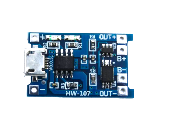
TP4056 1A Li-Ion Battery Charging Board Micro USB with Current Protection
The TP4056 includes built-in thermal regulation and current limiting, making it a great example of safe LDO-adjacent charging design for single cell Li-Ion batteries.
Practical Tips to Reduce LDO Heat in Your Projects
Beyond the calculations, here are actionable strategies Indian makers use to keep LDO regulators cool and reliable:
1. Reduce the Input Voltage
The single most effective way to reduce LDO heat is to lower VIN. If your load needs 3.3V, use a 5V adapter instead of 12V. The power dissipation drops dramatically. Pre-regulate with a cheap buck module when you must work from high voltages.
2. Use a Pre-Regulator Buck + LDO Combo
A common professional technique is to use a cheap switching buck converter (like the XL4016 or MP2307) to step down to 1–2V above the LDO output, then let the LDO handle final filtering and regulation. The buck handles most of the voltage drop efficiently (80–95%), and the LDO only dissipates a fraction of a watt while providing clean, low-noise output.
3. Copper Pour as Heatsink on PCB
For SMD packages like SOT-223 or D2PAK, adding a large copper pour connected to the thermal pad on both top and bottom layers of the PCB significantly reduces θJA. Many SOT-223 datasheets specify θJA values assuming a specific copper area — check your datasheet notes.
4. Derate Your Current
Never run an LDO at 100% of its rated current. Derate to 70–80% of maximum for reliable long-term operation in India’s high-ambient-temperature environment.
5. Select the Right Package
If your PD calculation shows 1W or more, choose a TO-220 or TO-263 (D2PAK) package from the start, not SOT-23 or SOT-223. The package choice is the single biggest factor in thermal performance.
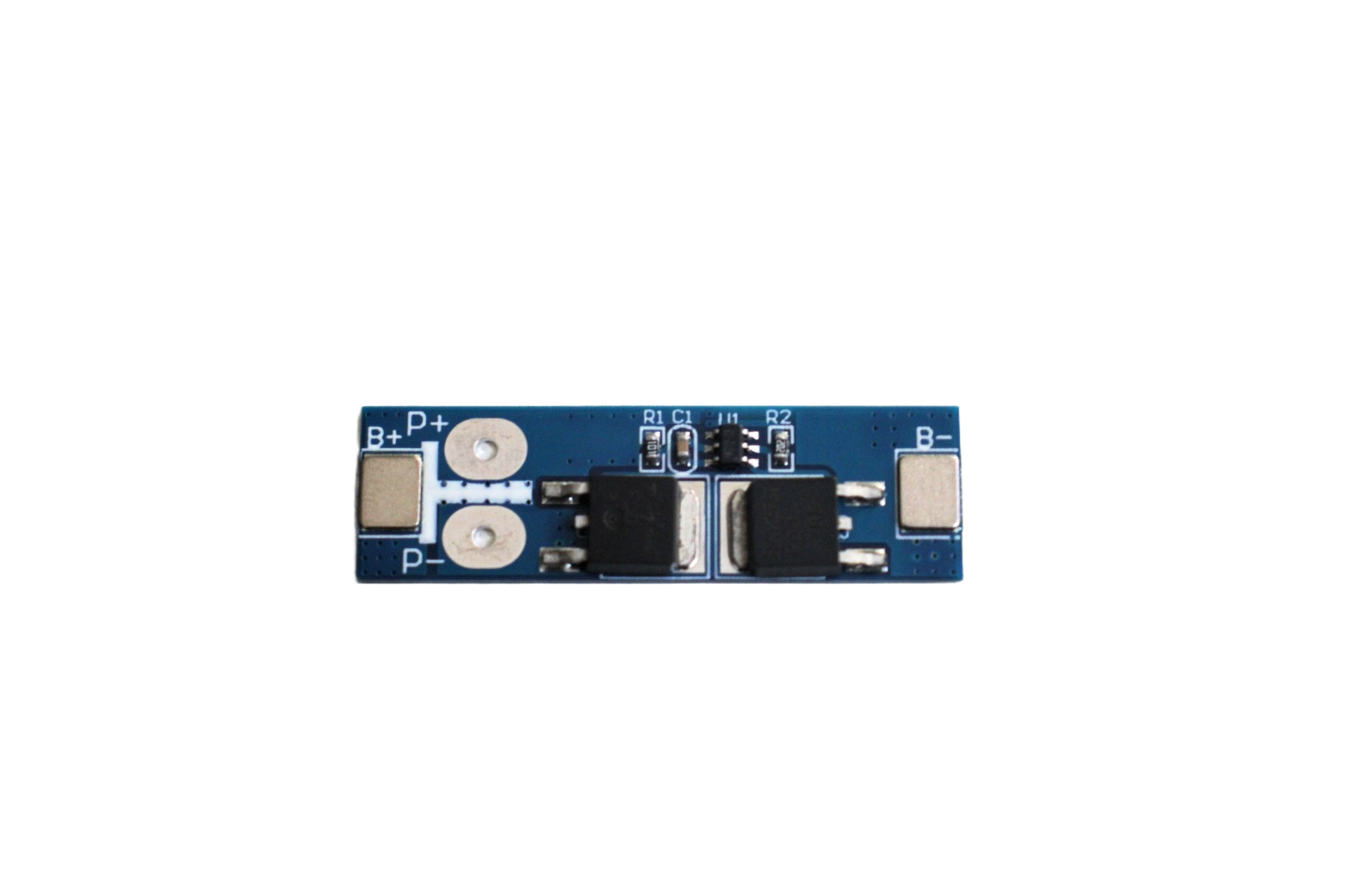
1S 12A 3.6V BMS Battery Protection Board for Li-ion Cell
This BMS board includes overcurrent and thermal protection features — essential for any battery-powered project where current and heat management are critical.

1S 18650 Li-ion Lithium Battery BMS Charger Protection Board for 3.7V Battery
Pair this BMS with your 18650-powered LDO circuit for complete overcurrent, overvoltage, and thermal protection of your power supply design.
Frequently Asked Questions
Why does my LDO get hot even at low currents?
Even at low load currents, if the input-to-output voltage difference is very large, power dissipation (PD = ΔV × I) can still be significant. Also check for quiescent current — some LDOs draw 5–10mA of quiescent current regardless of load, which adds up over a large voltage drop.
Can I parallel two LDOs to share the heat load?
Generally not recommended for LDOs without current-sharing circuitry. Due to slight variations in output voltage between units, one LDO will try to source more current than the other, defeating the purpose. Use a single higher-rated package or an SMPS instead.
What is the difference between thermal shutdown and current limiting?
Thermal shutdown is triggered by excessive junction temperature (typically above 125°C) and protects the IC from permanent damage by cutting the output. Current limiting is an electronic limit on output current, active even at normal temperatures, designed to protect downstream components from overload.
How does India’s climate affect LDO thermal calculations?
India’s ambient temperatures commonly reach 35–45°C indoors in summer, and over 55°C in industrial or outdoor enclosures. Always use TA = 40–50°C for your calculations rather than the 25°C assumed in most datasheets. This alone can add 15–25°C to your junction temperature estimate.
Is an AMS1117 reliable for continuous use?
Yes, if kept within its thermal limits. The AMS1117 has built-in current limiting and thermal shutdown. Keep junction temperature below 100°C for long-term reliability (not just below the 125°C absolute maximum). Add a small copper pour or TO-252 package for currents above 300mA.
Conclusion: Do the Math Before You Build
LDO regulator heat is not a mystery — it is pure physics. The power dissipation formula (PD = ΔV × I) and the junction temperature formula (TJ = TA + PD × θJA) give you everything you need to decide on the right package, heatsink, and input voltage before you ever solder a component. Given India’s high ambient temperatures, a few minutes of calculation can save you from hours of troubleshooting or a destroyed component.
Start every LDO-based design with these calculations, derate generously, and consider buck + LDO combos for high voltage differentials. Your circuits will be more reliable, run cooler, and last longer in the field.
Ready to build your next power supply project? Browse Zbotic’s full range of power modules, BMS boards, and charging ICs — all sourced and shipped across India.


Add comment