
From your TV remote to obstacle-avoiding robots, the humble infrared LED receiver circuit is everywhere in modern electronics. Invisible to the naked eye but detectable by sensors, infrared light enables wireless communication, proximity sensing, and remote control systems — all at a cost of just a few rupees per component. Whether you’re building an IR remote decoder, a line follower robot, or a motion-activated alarm, this guide covers everything you need to know about IR LEDs and receivers, including wavelengths, wiring, and working Arduino code.
Infrared Light Basics and Wavelengths
Infrared (IR) radiation occupies the electromagnetic spectrum just below visible light — between 700 nm and 1 mm wavelength. In electronics, we typically work with near-infrared (NIR) in the 700–1000 nm range, which can be generated by LEDs and detected by silicon-based photodetectors.
Human eyes cannot see IR light (the retina has no photoreceptors sensitive to wavelengths above ~700 nm), but your smartphone camera can — point your TV remote at your phone camera and press a button; you’ll see the IR LED flash purple-white. This is a handy debugging trick every Indian maker should know.
The most common wavelengths used in electronics projects:
- 850 nm: CCTV surveillance cameras, night-vision illuminators
- 940 nm: Consumer remote controls, obstacle sensors, proximity sensors — the most popular for Arduino projects
- 880 nm: Medical devices, industrial sensors
The 940 nm wavelength is dominant in hobbyist projects because it falls in a region where silicon photodetectors are highly sensitive while also being outside the visible spectrum, reducing interference from ambient light.
IR LED: Construction and Specifications
An infrared LED (IRED) works on the same principle as a visible-light LED — electrons recombine with holes in the semiconductor junction, releasing energy as photons. The difference is the semiconductor material: IR LEDs use gallium arsenide (GaAs) or gallium aluminium arsenide (GaAlAs), which emit photons in the 850–940 nm range instead of the visible spectrum.
Key Specifications to Check
| Parameter | Typical Value | Notes |
|---|---|---|
| Forward Voltage (Vf) | 1.1–1.5V | Lower than visible LEDs |
| Forward Current (If) | 20–100 mA | Continuous rating |
| Peak Pulse Current | 500–1000 mA | For brief modulated bursts |
| Wavelength | 940 nm (most common) | Match to receiver sensitivity |
| Half Angle | ±20° to ±60° | Narrower = farther range |
Calculating the Current-Limiting Resistor
Just like visible LEDs, IR LEDs need a series resistor to limit current. The formula is:
R = (Vsupply − Vf) / If
For a 5V Arduino supply, Vf = 1.2V, If = 20mA:
R = (5 − 1.2) / 0.02 = 190Ω → use 220Ω (next standard value)
IR Receiver Modules: TSOP, Photodiode, and Phototransistor
There are three main types of IR receivers used in maker projects, each suited to different applications:
1. TSOP-series Demodulating Receivers (TSOP1738, VS1838B)
These are integrated receiver modules that contain a photodiode, amplifier, bandpass filter, and demodulator all in one package. They are specifically designed for IR remote control reception at a carrier frequency of 36–38 kHz (38 kHz is most common). The output is a digital active-LOW signal — the pin goes LOW when the correct modulated IR signal is received.
The TSOP1738 and its clone VS1838B are the go-to choice for IR remote decoding with Arduino. They have three pins: VCC (2.5–5.5V), GND, and OUT (signal). Extremely easy to use — just connect them and point a remote control at them.
2. Photodiodes (BPW34, SFH203)
Bare IR photodiodes generate a small reverse current when illuminated by IR light. They require a transimpedance amplifier (op-amp) to convert the tiny photocurrent into a usable voltage. They offer fast response times and broad spectral sensitivity, making them suitable for high-speed data links (IrDA) and precision measurement.
3. Phototransistors
An IR phototransistor is a transistor whose base current is generated by incident IR light instead of an electrical signal. They amplify the received light signal internally and produce a cleaner output signal than bare photodiodes without needing an external amplifier. Many IR obstacle sensor modules use paired IR LED + phototransistor combinations.
Basic IR LED and Receiver Circuit
Here is the simplest possible IR communication circuit using discrete components:
Transmitter Side
- 5V supply → 220Ω resistor → IR LED (anode) → IR LED (cathode) → GND
- Or connect the 220Ω + IR LED in series from Arduino digital pin to GND
Receiver Side (using phototransistor)
- 5V → 10kΩ resistor → Phototransistor (collector)
- Phototransistor (emitter) → GND
- Output = junction between 10kΩ resistor and collector (voltage divider action)
When IR light hits the phototransistor, its collector-emitter resistance drops, pulling the output LOW. When no IR light is present, the 10kΩ pull-up keeps the output HIGH. This simple circuit forms the basis of all IR obstacle detection modules.

10CM Male To Male Breadboard Jumper Wires 2.54MM – 40Pcs
Essential for prototyping IR LED and receiver circuits on a breadboard. 40 colour-coded wires per pack.
Decoding IR Remote Signals with Arduino
Most consumer IR remotes (TV, AC, set-top box) use the NEC protocol, which modulates data at 38 kHz carrier frequency. Each button sends a unique 32-bit code. Using the IRremote library, you can decode these codes with just a TSOP1738 and an Arduino.
Hardware Setup
- TSOP1738 VCC → Arduino 5V
- TSOP1738 GND → Arduino GND
- TSOP1738 OUT → Arduino Digital Pin 11
- Add a 100Ω series resistor on VCC and a 10µF capacitor between VCC and GND close to the TSOP to filter power supply noise
Reading Remote Codes
#include <IRremote.hpp>
#define IR_RECEIVE_PIN 11

void setup() {
  Serial.begin(9600);
  IrReceiver.begin(IR_RECEIVE_PIN, ENABLE_LED_FEEDBACK);
  Serial.println("Point your remote and press a button...");
}
void loop() {
  if (IrReceiver.decode()) {
    Serial.print("Protocol: ");
    Serial.println(IrReceiver.decodedIRData.protocol);
    Serial.print("Code: 0x");
    Serial.println(IrReceiver.decodedIRData.decodedRawData, HEX);
    IrReceiver.resume(); // Ready for next signal
  }
}
Controlling an LED with TV Remote
#include <IRremote.hpp>
#define IR_PIN 11
#define LED_PIN 13
// Replace with your actual remote button code:
#define POWER_BTN 0xBF40FF00

bool ledState = false;
void setup() {
  IrReceiver.begin(IR_PIN, ENABLE_LED_FEEDBACK);
  pinMode(LED_PIN, OUTPUT);
}
void loop() {
  if (IrReceiver.decode()) {
    if (IrReceiver.decodedIRData.decodedRawData == POWER_BTN) {
      ledState = !ledState;
      digitalWrite(LED_PIN, ledState);
    }
    IrReceiver.resume();
  }
}
12V 5050 RGB LED Strip Controller with 24 Key IR Remote
A practical application of IR remote control — control RGB LED strips wirelessly. Great learning example for IR protocols.
IR Obstacle Sensor Circuit
IR obstacle detection is one of the most widely used applications in robotics. The principle is simple: an IR LED emits a beam, and if an object reflects it back to the IR receiver (phototransistor or photodiode), an obstacle is detected.
How IR Obstacle Sensor Modules Work
Prebuilt IR obstacle sensor modules (like the FC-51) contain:
- An IR LED (emitter) with a current-limiting resistor
- An IR photodiode/phototransistor (receiver)
- An LM393 comparator IC to threshold the received signal
- A potentiometer to adjust sensitivity
- Status LEDs for power and output
Typical detection range is 2–30 cm, adjustable via the onboard potentiometer. Output is digital: LOW when obstacle detected, HIGH when clear.
Building Your Own from Discrete Components
// Simple IR proximity detector
#define IR_SENSOR_PIN A0  // Phototransistor output
#define IR_LED_PIN 7

void setup() {
  pinMode(IR_LED_PIN, OUTPUT);
  Serial.begin(9600);
}
void loop() {
  // Emit IR pulse
  digitalWrite(IR_LED_PIN, HIGH);
  delayMicroseconds(100);
  int reflected = analogRead(IR_SENSOR_PIN);
  digitalWrite(IR_LED_PIN, LOW);

  // Read ambient (no IR)
  delayMicroseconds(100);
  int ambient = analogRead(IR_SENSOR_PIN);

  int signal = reflected - ambient; // Cancel out ambient IR
  Serial.print("Signal: "); Serial.println(signal);

  if (signal > 200) Serial.println("OBSTACLE DETECTED");
  delay(50);
}
Reading reflected minus ambient cancels out sunlight interference — a technique used in professional IR sensors.
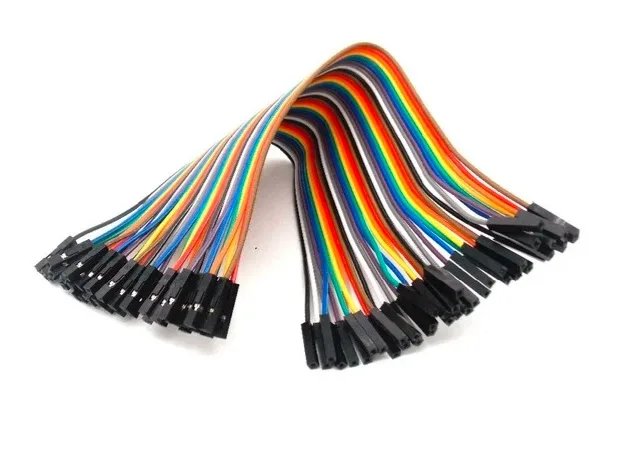
10CM Female To Female Breadboard Jumper Wires 2.54MM – 40Pcs
Ideal for connecting IR sensor modules (which have male header pins) to your Arduino or breadboard.
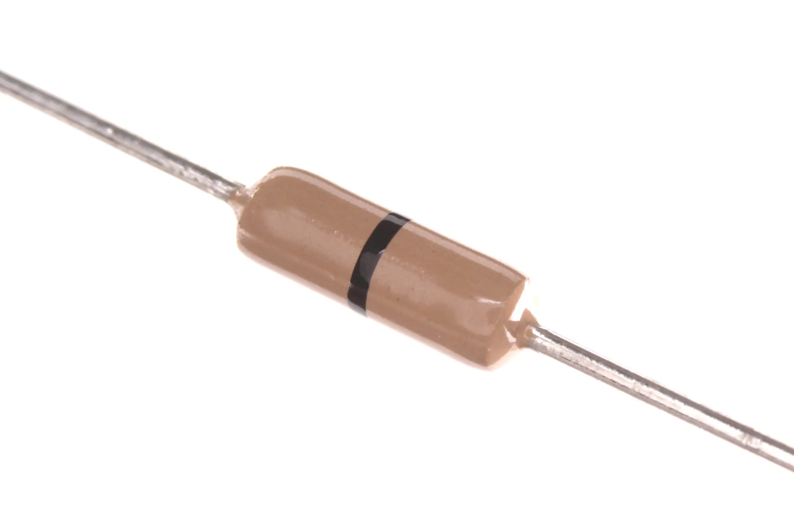
Carbon Film Resistors (Pack of 100)
220Ω and 10kΩ resistors are essential for IR LED current limiting and phototransistor pull-up circuits.
Troubleshooting and Tips
IR Not Working? Check These First
- Verify the IR LED is working: Use your phone camera to see if it flashes (point camera at LED and send signal)
- Check wavelength match: Your TSOP1738 expects 940 nm — make sure your IR LED is 940 nm and not 850 nm
- Carrier frequency: TSOP1738 = 38 kHz. If your remote uses 36 kHz or 56 kHz, get the right receiver variant
- Sunlight interference: Bright sunlight contains IR radiation that can saturate the receiver — test indoors or shade the sensor
- Power supply decoupling: A 10µF capacitor near the TSOP VCC pin prevents false triggers from power supply noise
- Distance: Typical reliable range for remote decoding is 3–8 meters. For obstacle detection, optimal range is 5–20 cm
Frequently Asked Questions
Q1: What is the difference between 850 nm and 940 nm IR LEDs?
850 nm LEDs are slightly visible (faint reddish glow) and are commonly used in security cameras and night-vision illuminators where higher output power is needed. 940 nm LEDs are completely invisible and are the standard choice for remote controls and obstacle sensors. Most TSOP-series receivers are optimized for 940 nm. Use the wavelength that matches your receiver’s peak sensitivity.
Q2: Can I use an IR LED for data communication?
Yes! IrDA (Infrared Data Association) standard allows data transfer up to 115 kbps (SIR) using IR LEDs. However, for practical maker projects, IR is better suited for one-way command transmission (remote control) rather than bidirectional data communication. For wireless data, use 433 MHz RF modules or Bluetooth/WiFi instead.
Q3: Why does my IR sensor stop working in sunlight?
Sunlight contains a broad spectrum including near-infrared. This ambient IR saturates the receiver’s front-end amplifier, making it unable to detect the modulated signal from your IR LED. TSOP-series receivers have built-in AGC (Automatic Gain Control) to partially mitigate this, but strong direct sunlight can still overwhelm them. Solutions: increase IR LED drive current for stronger signal, add a physical shield around the receiver, or use synchronous detection (sample before and after IR pulse, subtract the difference).
Q4: How far can I transmit with an IR LED?
Typical TV remotes work reliably at 5–10 meters. Maximum range depends on: IR LED output power, receiver sensitivity, ambient light conditions, and lens/reflector on the LED. For long-range IR links (>10m), use a high-power IR LED (100 mA+ pulsed current) with a narrow-angle (±10°) package and a focusing lens on the receiver.
Q5: What is the 38 kHz carrier frequency for?
IR remote controls modulate the actual data signal onto a 38 kHz carrier frequency before transmission. The TSOP receiver demodulates this carrier and outputs only the data envelope. This carrier modulation allows the receiver to distinguish intended remote signals from ambient IR noise (sunlight, incandescent bulbs) which is not modulated at 38 kHz. Think of it as a secret handshake the transmitter and receiver agree upon.
Build Your Next IR Project with Zbotic
Explore our full range of sensors, LEDs, and Arduino components — fast shipping across India, with quality guaranteed for every maker and student project.


Add comment