
Tri-State Logic: How Buses Share a Single Wire
Imagine you need ten different chips to share the same data line — but only one can drive that wire at any given moment. How do you keep the others from interfering? The answer is tri-state logic bus design, a fundamental technique that underlies almost every modern digital system: from the data bus inside a microprocessor to SPI flash memory to Arduino shields sharing the SPI pins. In this guide we explain tri-state logic from first principles, show you how bus arbitration works, and give you the practical knowledge to design reliable multi-device bus systems.
What Is Tri-State Logic?
Standard binary digital logic has exactly two states: logic HIGH (1) and logic LOW (0). Tri-state logic adds a third state: high impedance (Hi-Z), sometimes called the "floating" state or "disconnected" state.
In the high-impedance state, the output is effectively disconnected from the bus. It neither sources current (drives HIGH) nor sinks current (drives LOW). To the bus, a tri-state output in Hi-Z is invisible — as if the IC were not connected at all.
This third state is what makes shared buses possible. If you have 8 devices that all need to drive a single wire, you can:
- Permit only one device to be in the active state (HIGH or LOW) at any time
- Force all other devices into Hi-Z
- The active device controls the bus freely, with no conflict from the others
- Switch control to a different device by toggling Enable signals
Without tri-state, sharing a bus would be impossible with standard totem-pole outputs. One device driving HIGH and another driving LOW simultaneously would create a short circuit — the 5V rail fighting ground through low-impedance transistors, potentially destroying both ICs and certainly corrupting data.
The Three States Explained
Inside a tri-state output, there are three transistors (in a simplified model):
- P-type MOSFET (or PNP BJT): Connects output to VCC when conducting — drives HIGH
- N-type MOSFET (or NPN BJT): Connects output to GND when conducting — drives LOW
- Enable logic: When Enable is de-asserted, BOTH transistors are turned off simultaneously
The three states:
| State | Enable | Data Input | Output | Description |
|---|---|---|---|---|
| Logic HIGH | Active | 1 | VCC (≈5V) | PMOS on, NMOS off — sources current |
| Logic LOW | Active | 0 | GND (≈0V) | NMOS on, PMOS off — sinks current |
| Hi-Z | Inactive | X (any) | Floating | Both off — output disconnected |
The Hi-Z state has very high output impedance — typically several megaohms. The output appears as essentially an open circuit to the bus. Only the parasitic capacitance of the output pin remains, which is usually just a few picofarads.
The Enable Pin: Controlling Bus Access
Every tri-state output has an Enable (or Output Enable, OE) control pin. When the Enable is asserted (activated), the output drives the bus normally in HIGH or LOW based on the data input. When Enable is de-asserted, the output goes to Hi-Z.
Enable pins are typically active-low — they are labelled with an overline (OE̅) or a suffix like /OE, ~OE, or OEN. Active-low means Enable = 0 (LOW) → output is active, Enable = 1 (HIGH) → output is Hi-Z. This is a safety feature: if the enable line is floating (undefined), the output defaults to Hi-Z rather than actively driving the bus.
Example — the 74HC244 octal tri-state buffer:
- 8 data lines (1A1–1A4, 2A1–2A4 inputs)
- 8 tri-state outputs (1Y1–1Y4, 2Y1–2Y4)
- Two active-low output enable pins (1OE̅, 2OE̅)
- When 1OE̅ = LOW: outputs 1Y1–1Y4 actively drive the bus
- When 1OE̅ = HIGH: outputs 1Y1–1Y4 go Hi-Z, disconnecting from the bus
This IC (and similar: 74HC245 bidirectional, 74HC373 latch, 74HC374 flip-flop) is found everywhere data buses are used — memory interfacing, microprocessor buses, EPROM programmers, and bus expanders.
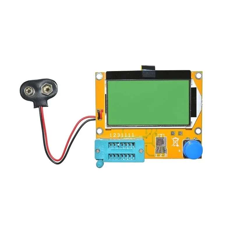
9V Battery Operated LCR-T4 12864 LCD Graphical Transistor Tester
When debugging tri-state bus circuits, identifying component values and transistor types quickly is essential. This all-in-one tester measures resistors, capacitors, inductors, transistors, MOSFETs, and more — indispensable for any electronics lab bench.
Bus Arbitration and Conflict Prevention
Bus arbitration is the process of deciding which device gets to drive the bus at any given moment — ensuring only one active driver while all others remain in Hi-Z. Getting this wrong causes bus contention — two outputs fighting each other — which is harmful to both the ICs and the signal integrity.
Types of bus arbitration:
1. Centralized (Master-Controlled) Arbitration
A single master controller (typically a microcontroller or FPGA) controls all Enable signals. It activates one device at a time through GPIO or decoded address lines. The master guarantees mutual exclusion by design — it never enables two conflicting devices simultaneously. This is how most memory-mapped IO works on embedded systems.
2. Chip Select (SPI Bus)
SPI uses tri-state in a specific way. All SPI slaves connect their MISO (Master In Slave Out) lines together. Only the selected slave drives MISO; all others keep their MISO in Hi-Z. The CS̅ (Chip Select, active-low) pin of each slave serves as its Enable pin. The master asserts one CS̅ at a time — only that device drives the shared MISO line.
3. Bus Contention — The Problem to Avoid
Bus contention occurs when two tri-state outputs are both active simultaneously. The result:
- If both drive the same level: no damage, but wasted current
- If they drive opposite levels: a short circuit between VCC and GND through the output transistors. Current is limited only by the on-resistance of the transistors (typically a few ohms to tens of ohms). This causes excessive heat, possible IC damage, and definitely corrupted data
On modern CMOS ICs, brief contention during switching is somewhat tolerable due to higher output impedance — but sustained contention will damage the IC and must be avoided by design.
Common Tri-State ICs and Their Uses
| IC | Function | Typical Use |
|---|---|---|
| 74HC244 | Octal buffer/driver, non-inverting | Data bus drivers, address buffers |
| 74HC245 | Octal bidirectional transceiver | Bidirectional data buses, level shifters |
| 74HC373 | Octal D-latch with tri-state output | Multiplexed address/data bus (e.g., 8051) |
| 74HC374 | Octal D flip-flop with tri-state output | Registered bus interfaces |
| 74HC125 | Quad buffer, individual enables | Small bus multiplexers |
| 74HC126 | Quad buffer, active-high enable | Bus control with active-high logic |
Tri-State in Microcontroller and SPI Systems
In the Arduino and ESP32 world, tri-state logic appears in several forms:
SPI Bus Sharing
Multiple SPI devices (SD card, OLED display, RF module) share MOSI, MISO, and SCK lines. Each has a separate CS̅ pin. Only the device with CS̅ asserted LOW drives MISO. The others keep MISO in Hi-Z. This is textbook tri-state bus operation — managed automatically by the SPI protocol and each device’s hardware.
GPIO as Tri-State
All microcontroller GPIO pins support three states: output HIGH, output LOW, and input mode (Hi-Z). When you set a pin as an input (`pinMode(pin, INPUT)` in Arduino), you are putting the GPIO into Hi-Z mode. This is how you release control of a shared signal line. Setting a pin as INPUT_PULLUP adds an internal pull-up resistor (~50 kΩ on Arduino Uno) to prevent the line from floating.
8-bit Parallel Buses
When connecting character LCD modules (like the HD44780) in 4-bit or 8-bit mode, or interfacing SRAM and EEPROM chips to a microcontroller, tri-state buffers (74HC245) are commonly used to prevent bus contention and allow the microcontroller GPIO to communicate with the memory’s data bus without permanent connection.
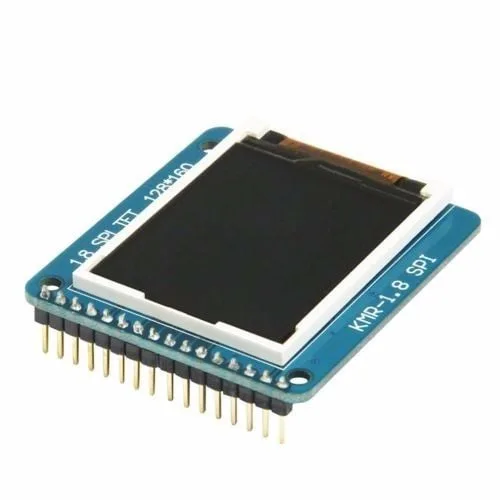
1.8 Inch SPI 128×160 TFT LCD Display Module for Arduino
This TFT display uses SPI — a perfect real-world tri-state bus example. Multiple SPI devices share MOSI/MISO/SCK lines with individual CS pins controlling which device is active at any time.
Floating Bus Problem and Pull Resistors
When all tri-state outputs are in Hi-Z simultaneously, the bus is floating. A floating bus picks up noise, oscillates, or slowly drifts — causing false data reads, spurious interrupts, and unpredictable behaviour. This is a real problem during system startup (before software configures everything) or during bus transitions.
Solutions to the floating bus problem:
- Pull-up or pull-down resistors: Connect the bus to VCC (pull-up) or GND (pull-down) through resistors (typically 10 kΩ). When all drivers are Hi-Z, the bus settles to a known defined state. The pull resistors are weak enough that an active driver easily overrides them.
- Bus keeper or bus-hold circuits: A weak latching circuit (two back-to-back inverters) that "remembers" the last driven value when the bus becomes Hi-Z. Found in some FPGA IO pins and specific bus ICs. Consumes negligible power and does not slow transitions the way pull resistors can.
- Design arbiter so bus is never fully released: Ensure your arbitration logic always hands off from one driver to another without an intermediate floating period. Overlap enable timing slightly — but be careful not to cause contention.
![1.5 Ohm [0.25W] 1/4W Metal Film Resistor MFR (Pack of 100)](https://cdn.zbotic.in/wp-content/uploads/2021/02/AI0248.jpg.webp)
1.5 Ohm [0.25W] 1/4W Metal Film Resistor MFR (Pack of 100)
Metal film resistors offer better precision and lower noise than carbon film — important for bus termination and pull-up/pull-down applications where accurate resistance values prevent floating-bus problems.

10CM Male To Male Breadboard Jumper Wires 2.54MM – 40Pcs
Build tri-state bus experiments with confidence using quality male-to-male jumper wires. Colour-code your bus lines (data, address, control) for easy debugging when working with multi-device bus systems.
Frequently Asked Questions
Can I measure Hi-Z state with a multimeter?
A multimeter in voltage mode has very high input impedance (~10 MΩ). If the bus has pull-up or pull-down resistors, you will measure the pull resistor voltage (close to VCC or GND). If the bus is completely floating with no pull resistors, the multimeter reading will be undefined — it may read mid-supply, or drift around, or show the supply voltage due to the meter’s own leakage. A logic probe is more useful: it shows three states (HIGH, LOW, and HIGH IMPEDANCE/floating).
Is tri-state the same as open collector?
No, though they are related. Open collector can also effectively disconnect from the bus (by turning the transistor off), but it can only actively pull LOW — the "high" state is passive (through a pull-up). Tri-state outputs can actively drive BOTH HIGH and LOW states, and also go to Hi-Z. Tri-state offers faster high-going transitions (active drive up) vs open collector (passive pull-up limited by RC time constant).
What happens during bus contention in modern CMOS ICs?
In modern CMOS logic, the output drivers have low on-resistance (typically 10–50 Ω). When two outputs fight each other (one HIGH, one LOW), the shoot-through current is (VCC / R_total) ≈ (5V / 20Ω) = 250 mA peak. This heats the IC rapidly. Brief glitches (a few nanoseconds during switching) are usually tolerable. Sustained contention for milliseconds or longer will damage the IC. CMOS is less tolerant of contention than old TTL, which had higher output impedances.
Why do CPUs need tri-state for their data bus?
A modern CPU communicates with RAM, ROM, IO devices, and peripherals over shared bus lines. At any moment, only one device should drive the data bus — for example, RAM driving data to the CPU, or the CPU writing to a peripheral. Tri-state allows each device to sit quietly in Hi-Z until its turn. Without tri-state, you would need separate dedicated point-to-point wires for every device pair — physically impossible for complex systems.
Does SPI have bus contention risks?
Yes, if CS̅ pins are managed incorrectly. If two SPI slaves both have CS̅ asserted simultaneously, both will drive MISO — causing contention. This is why SPI masters must ensure only one CS̅ is active at a time, and must properly de-assert (return to HIGH) the previous device’s CS̅ before asserting the next device. Sloppy firmware that enables multiple devices simultaneously will corrupt data and may damage ICs.
Design Your Next Bus System with Components from Zbotic
From resistors and capacitors for bus termination to display modules, microcontroller boards, and measurement tools — Zbotic has everything Indian makers need to build reliable digital systems. Explore our full electronics catalogue and get fast delivery across India.


Add comment