
I2C Communication: Multiple Devices on Same Bus Arduino Guide
When you start building Arduino projects beyond a single sensor, you quickly discover the power of I2C multiple devices Arduino setups. I2C (Inter-Integrated Circuit) lets you daisy-chain dozens of sensors, displays, and modules using just two wires — SDA and SCL — saving precious GPIO pins on your Uno, Mega, or Nano. Whether you are connecting an OLED display alongside a temperature sensor, or building a multi-node data logger, mastering I2C multi-device communication is an essential skill for every Indian maker and hobbyist.
What Is I2C and How Does It Work?
I2C, pronounced “eye-squared-C”, is a synchronous serial communication protocol originally developed by Philips (now NXP Semiconductors). It uses only two bidirectional lines: SDA (Serial Data) and SCL (Serial Clock). This makes it extremely popular in embedded systems where pin count is at a premium.
The protocol operates on a master-slave architecture. In a typical Arduino project, the Arduino acts as the master and all connected sensors, displays, and modules act as slaves. The master initiates all communication by generating clock signals on SCL and addressing specific slaves using a unique 7-bit or 10-bit address.
Key characteristics of I2C:
- Two-wire interface: SDA (data) + SCL (clock)
- Speed modes: Standard (100 kHz), Fast (400 kHz), Fast-Plus (1 MHz)
- Addressing: Up to 128 devices on one bus (7-bit address space)
- Pull-up resistors: Typically 4.7kΩ for 100 kHz, 2.2kΩ for 400 kHz
- Arduino pins: A4 (SDA) and A5 (SCL) on Uno/Nano; pins 20/21 on Mega
The beauty of I2C for multi-device setups is that all devices share the same two wires. Each device is identified solely by its address, and the master selects which device to talk to by transmitting that address at the start of each transaction.
I2C Addresses: The Foundation of Multi-Device Setup
Every I2C device has a fixed base address defined by its manufacturer. For example, the popular SSD1306 OLED display typically uses address 0x3C or 0x3D. The AHT10 temperature/humidity sensor defaults to 0x38. The MPU-6050 gyroscope uses 0x68 or 0x69.
Many devices allow you to change the last 1–3 bits of their address by pulling specific address pins (A0, A1, A2) high or low. The PCF8574 I/O expander, for instance, supports 8 different addresses (0x20 to 0x27) by configuring three address pins — meaning you can connect up to 8 of the same module on a single bus.
Common I2C addresses for popular modules:
- SSD1306 OLED:
0x3C/0x3D - BMP280 pressure sensor:
0x76/0x77 - DS3231 RTC:
0x68 - MPU-6050 IMU:
0x68/0x69 - AHT10/AHT20:
0x38 - PCF8574 I/O expander:
0x20–0x27 - AT24C series EEPROM:
0x50–0x57
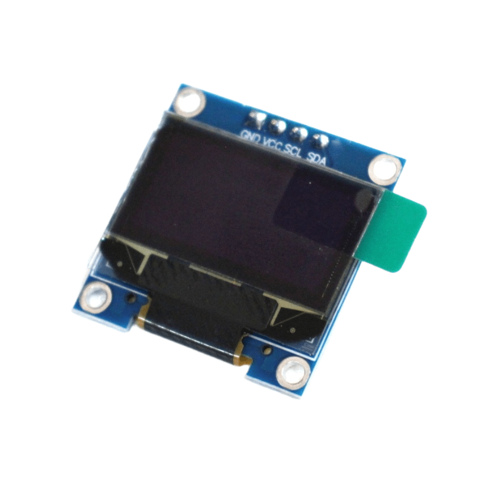
0.96 Inch I2C OLED LCD Module – SSD1306 (White)
A classic 4-pin I2C OLED display at address 0x3C. Perfect for displaying sensor data in multi-device I2C projects. Very low power draw.
Wiring Multiple I2C Devices to Arduino
Connecting multiple I2C devices to an Arduino is straightforward — all devices share the same SDA and SCL lines. Here is a step-by-step wiring guide:
Hardware connections (Arduino Uno/Nano):
- All device SDA pins → Arduino A4 (SDA)
- All device SCL pins → Arduino A5 (SCL)
- All device GND → Arduino GND
- All device VCC → Arduino 3.3V or 5V (check device datasheet)
Pull-up resistors: Most breakout boards already include onboard pull-up resistors. If you are connecting bare ICs, add external 4.7kΩ resistors from SDA to VCC and SCL to VCC. Too many pull-up resistors on the bus can cause issues — if you have more than 3–4 modules each with their own pull-ups, consider removing the redundant ones or reducing values.
Voltage level considerations: Arduino Uno/Nano operates at 5V, while many modern sensors (like the BMP280 or SHT31) are 3.3V devices. Always use a bi-directional level shifter for mixed-voltage I2C buses to avoid damaging 3.3V devices. The bus voltage is determined by the pull-up resistor connection point.
Wire length: Keep I2C wires short (under 30 cm for reliable operation at 400 kHz). For longer distances, reduce bus speed to 100 kHz or use I2C repeaters/buffers.
Resolving I2C Address Conflicts
Address conflicts occur when two or more devices share the same I2C address, causing communication failures. This is one of the most common headaches when connecting I2C multiple devices on Arduino projects.
Strategy 1: Use address pins. Check if your device has configurable address pins (A0, A1, A2). For example, two BMP280 sensors can coexist at 0x76 and 0x77 by pulling the SDO pin low or high respectively.
Strategy 2: Use a TCA9548A multiplexer. If you must use multiple devices with the same fixed address (like two SSD1306 OLEDs), a multiplexer routes I2C traffic to isolated sub-buses. Covered in detail in the next section.
Strategy 3: Software I2C on different pins. Libraries like SoftWire or Wire.h on ESP32/STM32 allow creating multiple I2C buses on different GPIO pins, each with its own device set.
Strategy 4: I2C address translators. ICs like the LTC4316 translate one fixed address to another, allowing two identical devices to coexist on the same bus without a multiplexer.
Using the I2C Scanner Sketch
Before writing any device-specific code, always run the I2C scanner sketch to discover all connected device addresses. This is an invaluable debugging tool that every Arduino maker should know.
#include <Wire.h>

void setup() {
  Wire.begin();
  Serial.begin(9600);
  Serial.println("I2C Scanner - Scanning...");

  byte count = 0;
  for (byte addr = 1; addr < 127; addr++) {
    Wire.beginTransmission(addr);
    if (Wire.endTransmission() == 0) {
      Serial.print("Found device at address: 0x");
      if (addr < 16) Serial.print("0");
      Serial.println(addr, HEX);
      count++;
    }
  }
  if (count == 0)
    Serial.println("No I2C devices found.");
  else
    Serial.print(count); Serial.println(" device(s) found.");
}

void loop() {}
Upload this to your Arduino, open the Serial Monitor at 9600 baud, and you will see the hex addresses of all connected devices. If a device you wired up does not appear, check your SDA/SCL connections, pull-up resistors, and power supply.
Using a TCA9548A I2C Multiplexer
The TCA9548A (also called PCA9548A) is the go-to solution when you need multiple devices with the same I2C address. It provides 8 independent I2C sub-buses controlled by a single master bus, and itself sits at addresses 0x70–0x77.
How it works: You send a control byte to the TCA9548A to enable one or more of its 8 channels. Any subsequent I2C communication on the master bus is forwarded only to the enabled sub-bus(es). Other channels remain electrically isolated.
#include <Wire.h>

#define TCA_ADDR 0x70

void tcaSelect(uint8_t channel) {
  if (channel > 7) return;
  Wire.beginTransmission(TCA_ADDR);
  Wire.write(1 << channel); // enable channel
  Wire.endTransmission();
}

void setup() {
  Wire.begin();
  Serial.begin(9600);

  // Talk to OLED on channel 0
  tcaSelect(0);
  // initialize oled1...

  // Talk to OLED on channel 1
  tcaSelect(1);
  // initialize oled2...
}

void loop() {
  tcaSelect(0);
  // write to oled1...

  tcaSelect(1);
  // write to oled2...
}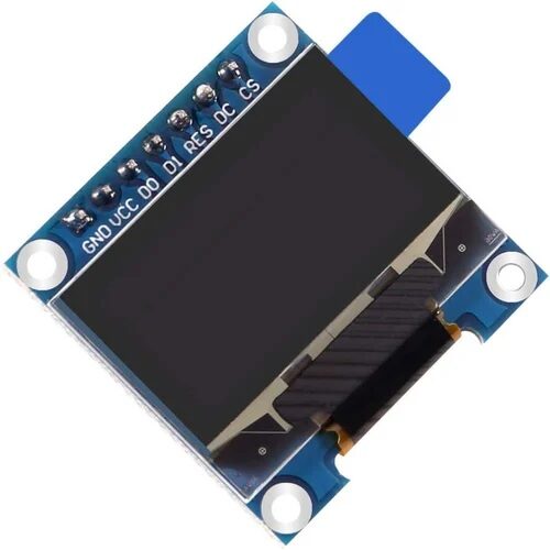
0.96 Inch SPI OLED LCD Module – 7-pin SSD1306 (White)
When you need two displays and I2C addresses conflict, switch one to SPI mode. This 7-pin OLED uses SPI for faster refresh and no address clashes.
Arduino Code Examples for Multiple I2C Devices
Here is a practical example reading from an SSD1306 OLED (0x3C) and a BMP280 sensor (0x76) simultaneously on the same I2C bus:
#include <Wire.h>
#include <Adafruit_SSD1306.h>
#include <Adafruit_BMP280.h>

Adafruit_SSD1306 display(128, 64, &Wire, -1);
Adafruit_BMP280 bmp;

void setup() {
  Wire.begin();  // SDA=A4, SCL=A5 on Uno
  Wire.setClock(400000); // 400 kHz Fast Mode

  display.begin(SSD1306_SWITCHCAPVCC, 0x3C);
  display.clearDisplay();

  bmp.begin(0x76);
}

void loop() {
  float temp = bmp.readTemperature();
  float pressure = bmp.readPressure() / 100.0F;

  display.clearDisplay();
  display.setTextSize(1);
  display.setTextColor(SSD1306_WHITE);
  display.setCursor(0, 0);
  display.print("Temp: "); display.print(temp); display.println(" C");
  display.print("Press: "); display.print(pressure); display.println(" hPa");
  display.display();

  delay(2000);
}
Tips for robust multi-device I2C code:
- Always initialize
Wire.begin()before any device library inits - Set clock speed with
Wire.setClock(400000)only after Wire.begin() - Check return values from
beginTransmission()for error handling - Use
Wire.setTimeout()to avoid infinite hangs if a device stops responding - On ESP32, you can use
Wire.begin(SDA_PIN, SCL_PIN)to use any GPIO pins
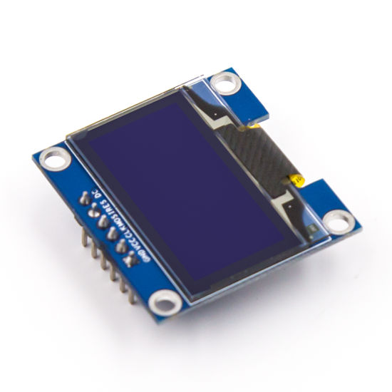
0.96 Inch SPI OLED LCD Module – 6-pin SSD1306 (Blue)
A compact 6-pin blue OLED display ideal for multi-sensor dashboards. SPI interface frees up your I2C bus for other devices.
Troubleshooting I2C Issues
Even experienced makers run into I2C problems. Here are the most common issues and fixes:
Problem: I2C scanner shows no devices
Fix: Check SDA/SCL wiring, ensure pull-up resistors are present (4.7kΩ), verify power supply, confirm device is not in a fault state by power cycling.
Problem: Communication fails intermittently
Fix: Reduce bus speed from 400 kHz to 100 kHz. Shorten wire lengths. Check for noise sources near I2C wires. Verify pull-up resistor values are appropriate for bus capacitance.
Problem: Device address not found after adding second device
Fix: Confirm each device has a unique address. Use I2C scanner to check. If same address, use address pins or a multiplexer.
Problem: Arduino freezes during I2C communication
Fix: This indicates a bus lockup. A stuck SDA line (held low by a device) prevents the master from sending a START condition. Power cycle all devices. Some libraries provide a Wire.clearWireTimeoutFlag() method. Consider adding a hardware I2C reset circuit.
Problem: 5V Arduino damaging 3.3V sensors
Fix: Use a bidirectional level shifter module. I2C is open-drain — with proper level shifting, 5V and 3.3V devices can coexist safely.
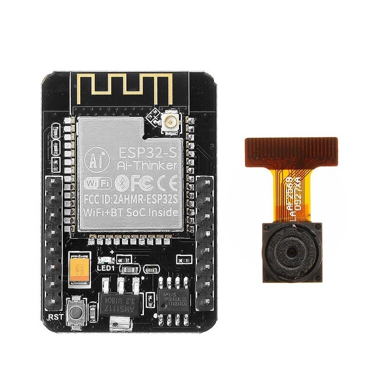
Ai Thinker ESP32-CAM Development Board
ESP32 natively supports two separate I2C buses, making it ideal for complex multi-device setups. Includes WiFi and Bluetooth for IoT projects.
Frequently Asked Questions
How many I2C devices can I connect to one Arduino?
Theoretically, up to 128 devices on a single bus (7-bit addressing). In practice, bus capacitance limits you to around 10–15 modules with standard pull-ups. Using a TCA9548A multiplexer effectively multiplies this limit 8x. Ensure adequate power supply current for all devices.
Can I use I2C and SPI at the same time on Arduino?
Yes. I2C uses A4/A5 (Uno) and SPI uses pins 10-13 (SS, MOSI, MISO, SCK). They are completely independent and can run simultaneously. Many projects combine an I2C sensor with an SPI display or SD card reader.
What happens if two I2C devices have the same address?
Both devices respond simultaneously when addressed, causing data corruption and bus errors. Your program will receive garbled data or no response at all. You must resolve this using address pins, a multiplexer, or running one device on a separate I2C bus.
Do I need pull-up resistors for each I2C device?
You only need one pair of pull-up resistors for the entire bus, not per device. Most breakout boards include them. If you use many modules each with their own resistors, the combined parallel resistance drops too low and can cause signal integrity issues. Remove pull-up resistors from extra modules when connecting many devices.
Is I2C suitable for long distance communication in my project?
I2C is designed for short-distance on-board or near-board communication. For reliable operation, keep total wire length under 1 meter at 100 kHz. For distances beyond 1–2 meters, consider using I2C over UART bridges, RS-485, or CAN bus instead.
Build Your Multi-Sensor I2C Project Today!
Zbotic stocks a wide range of I2C-compatible modules — OLED displays, sensors, and development boards — delivered fast across India.


Add comment