
I2C Bus Pullup Resistors: Value Selection & Common Mistakes
One of the most overlooked aspects of building reliable Arduino, ESP32, or Raspberry Pi projects is correct I2C pullup resistor value selection. Too high and your bus slows to a crawl with corrupted data; too low and your microcontroller’s output stages overheat. Yet the I2C spec allows values anywhere from 1 kΩ to 47 kΩ depending on bus speed and capacitance—so how do you pick the right one? This guide covers the theory, the math, and the practical rules every Indian maker needs to know before connecting an OLED, RTC, IMU, or GPIO expander to their I2C bus.
How I2C Pullups Actually Work
I2C is an open-drain bus. Neither the master (your Arduino or ESP32) nor any slave device ever actively drives the line HIGH. Instead, every device can only pull the line LOW (to ground) or release it. When all devices release the line, the pullup resistors pull it back HIGH through the positive supply voltage (typically 3.3 V or 5 V).
This architecture means:
- If you forget the pullups entirely, the bus floats and you’ll get random 0xFF or 0x00 reads all day long.
- If the pullup is too weak (too high resistance), the rising edge is too slow and the bus violates timing specs at higher speeds.
- If the pullup is too strong (too low resistance), the sink current through the open-drain driver exceeds the device’s rating and causes overheating or logic errors.
Both SDA and SCL lines require their own independent pullup resistors. A common mistake is using only one resistor or sharing it between both lines—this will never work correctly.
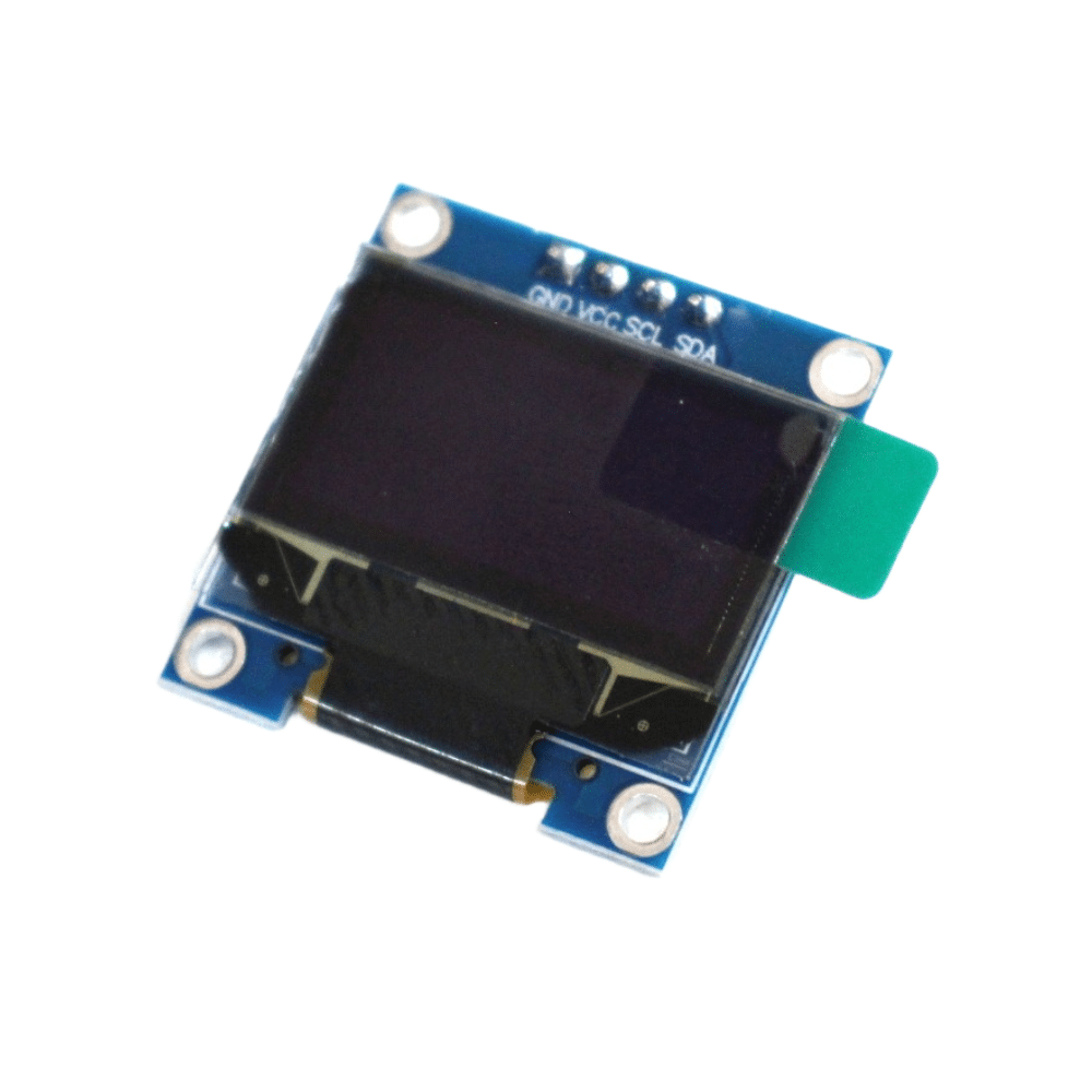
0.96 Inch I2C OLED LCD Module 4-pin White SSD1306
The most popular I2C display for maker projects. Comes with 4.7 kΩ pullups already fitted on the breakout — you can directly connect to 3.3 V or 5 V Arduino/ESP32 boards.
The Math: Calculating the Right Resistance
The I2C specification (UM10204 Rev 7) gives two constraints that define the safe range of your pullup resistor:
Minimum Resistance (Maximum Current)
Each open-drain output can sink a maximum of 3 mA (standard mode / fast mode) before the output voltage rises above VOL(max) = 0.4 V. At 3.3 V supply:
R_min = (VCC - V_OL) / I_sink_max
R_min = (3.3V - 0.4V) / 3mA = 2.9V / 0.003A ≈ 967 Ω → use 1 kΩ minimum
At 5 V:
R_min = (5V - 0.4V) / 3mA = 4.6V / 0.003A ≈ 1533 Ω → use 1.8 kΩ minimumMaximum Resistance (Rise Time)
The I2C spec requires the bus to rise from 0.3×VCC to 0.7×VCC within the rise time budget (tr). The dominant factor is the RC time constant formed by the pullup resistor and the total bus capacitance. For Standard Mode (100 kHz), tr max = 1000 ns; for Fast Mode (400 kHz), tr max = 300 ns.
R_max = t_rise / (0.847 × C_bus)

// Standard Mode, 100 pF bus capacitance:
R_max = 1000ns / (0.847 × 100pF) = 11.8 kΩ

// Fast Mode, 100 pF bus capacitance:
R_max = 300ns / (0.847 × 100pF) = 3.5 kΩ
Bus Speed and Resistor Value: The Trade-off
Armed with the formulas above, here’s a practical table for the most common scenarios Indian makers encounter:
| Bus Speed | VCC | Bus Cap. | Recommended R | Notes |
|---|---|---|---|---|
| Standard (100 kHz) | 5 V | 50 pF | 4.7 kΩ | 1–2 devices, short wires |
| Standard (100 kHz) | 3.3 V | 50 pF | 4.7 kΩ | Most common for ESP32 |
| Standard (100 kHz) | 3.3 V | 200 pF | 2.2 kΩ | Long cables, 5+ devices |
| Fast Mode (400 kHz) | 3.3 V | 50 pF | 2.2 kΩ | OLED + IMU combos |
| Fast Mode+ (1 MHz) | 3.3 V | 50 pF | 1 kΩ | High-speed sensors only |
5 Common Pullup Mistakes and How to Avoid Them
Mistake 1: Double Pullups (Most Common!)
You buy a breakout board—say an OLED or an MPU-6050 module—and it already has 4.7 kΩ pullups onboard. You then add your own 4.7 kΩ on your main board. Result: two 4.7 kΩ resistors in parallel = 2.35 kΩ effective pullup. Add a third device and you’re at 1.57 kΩ. This isn’t always a problem at 100 kHz, but it can push sink current above 3 mA at 5 V. Check your breakout schematics or measure the pull strength with a multimeter before adding external resistors.
Mistake 2: Wrong Voltage Level Mixing
Connecting a 5 V Arduino to a 3.3 V device (like an ESP32 or a 3.3 V-only sensor) through I2C without a level shifter is dangerous. Even with the open-drain topology, if both sides pull up to their own VCC, you can have 5 V on the SCL/SDA lines of a device rated only for 3.3 V. Use a bidirectional level shifter or a resistor voltage divider on the data lines.
Mistake 3: Using 10 kΩ at 400 kHz
A 10 kΩ pullup at 400 kHz with even 100 pF bus capacitance gives a rise time of ~1 µs—more than 3× the 300 ns budget. Your oscilloscope will show a rounded, triangular waveform instead of square pulses. The bus will appear to “work” at low data volume but fail intermittently under heavy traffic. Always use 2.2 kΩ or lower for Fast Mode.
Mistake 4: Not Accounting for PCB/Cable Capacitance
Every centimetre of PCB trace adds roughly 1–2 pF of capacitance. A jumper cable adds 50–100 pF per metre. If you’re using 30 cm Dupont wires to connect your I2C sensor module, you’ve added up to 30 pF of bus capacitance on top of device input capacitances. Always measure or estimate total bus capacitance before choosing the final resistor value.
Mistake 5: Connecting Pullups to an Always-On Supply
When you power off your microcontroller but leave the sensors powered (or vice versa), current can flow backward through the I2C lines and power latch-up or damage a device. Tie your pullup resistors to the same supply rail that powers all I2C devices simultaneously, or use a load switch to cut power to the entire I2C bus.
Multiple Devices and Long Cables
Each I2C device adds its own input capacitance (typically 5–15 pF) and any cable connecting them adds more. As you add devices, the total capacitance rises and you must reduce the pullup resistance accordingly:
- Up to 3 devices, 10 cm wires: 4.7 kΩ at 100 kHz, 2.2 kΩ at 400 kHz
- 4–8 devices or up to 30 cm wires: 2.2 kΩ at 100 kHz, 1.8 kΩ at 400 kHz
- Beyond 8 devices or cables over 50 cm: Consider an I2C bus multiplexer (TCA9548A) + buffer (PCA9615) to reset capacitance at each segment
For very long runs (over 1 m), the I2C bus is simply not designed for it. Use RS-485 or UART with repeaters instead, or choose an I2C bus extender IC (P82B96 or PCA9600) that can drive capacitive loads up to 4 nF.
Can You Use Internal Pullups?
Arduino and ESP32 microcontrollers have internal pullup resistors that can be enabled on I2C pins. However, these are designed for GPIO use and are typically 20–50 kΩ—far too high for reliable I2C communication above very short distances and low speeds. The Arduino Wire library does NOT enable them by default. If you rely on them for a two-device system with 5 cm wires, it may appear to work, but you’re operating outside spec. Always use discrete external resistors for any real project.
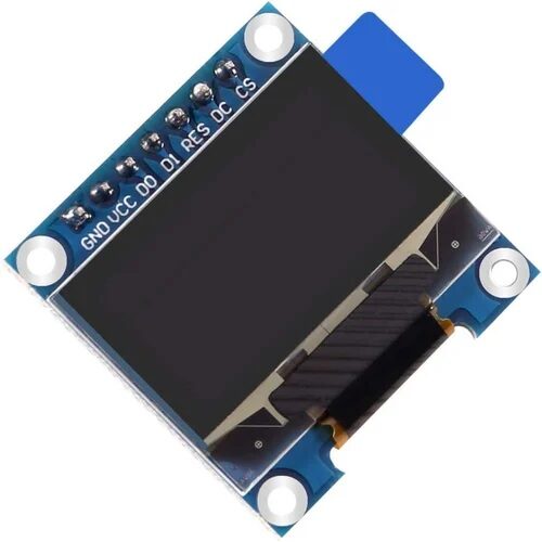
0.96 Inch SPI OLED LCD Module 7-pin SSD1306 White
If I2C pullup headaches are getting you down, switch to SPI! This 7-pin OLED uses the SPI interface — no pullup resistors needed, faster refresh, and no bus address conflicts.
Quick Reference: Which Value to Use
If you don’t want to do the math every time, follow these rules of thumb that cover 95% of maker projects:
- 3.3 V bus, 100 kHz, 1–3 devices, short wires (under 20 cm): Use 4.7 kΩ. This is the sweet spot used on most breakout boards.
- 5 V bus, 100 kHz, 1–3 devices: Use 4.7 kΩ. Same value works because the higher voltage partially compensates for the lower sink threshold.
- Any voltage, 400 kHz: Use 2.2 kΩ. Do not use 4.7 kΩ for reliable operation.
- Long cables, many devices: Use 1.8 kΩ or 1 kΩ and verify with an oscilloscope.
- Check for existing onboard pullups before adding your own! Two sets of 4.7 kΩ = 2.35 kΩ, which is fine for 400 kHz but may surprise you.
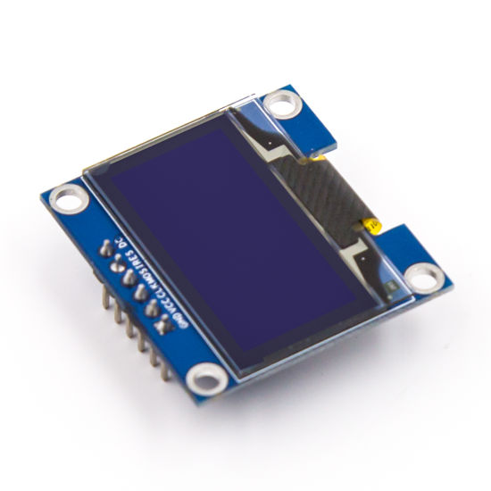
0.96 Inch SPI OLED LCD Module 6-pin Blue SSD1306
Blue SSD1306 OLED in 6-pin SPI format. Great for debugging I2C bus issues — connect this via SPI to verify your display is working while you troubleshoot the I2C wiring separately.
Frequently Asked Questions
Why does my I2C device scan show 0x00 or 0x7F for every address?
This almost always means the pullup resistors are missing or disconnected. Without pullups, the bus floats and the scanner reads garbage. Double-check that both SDA and SCL have pullups to the supply voltage, and verify your wiring with a continuity tester.
Can I use the same pullup resistor value for 3.3 V and 5 V systems?
Yes, 4.7 kΩ works acceptably in both voltage rails for Standard Mode (100 kHz) with a small number of devices. The sink current at 5 V with 4.7 kΩ is approximately (5-0.4)/4700 = 0.98 mA, well within the 3 mA maximum. The minimum resistance at 5 V is 1.8 kΩ, so 4.7 kΩ leaves comfortable headroom.
My I2C bus works fine at room temperature but fails when it gets hot. Why?
High temperature increases leakage currents in semiconductor junctions and reduces the open-drain transistor’s current sinking ability. The effective sink current decreases, making it harder to pull the line reliably to the VOL level. At high temperatures, use a slightly lower pullup value (e.g., 3.3 kΩ instead of 4.7 kΩ) to ensure more decisive LOW levels.
Do I need pullup resistors for I2C over longer distances?
Yes, and you should use lower values (1.8–2.2 kΩ) to compensate for increased capacitance. However, I2C is fundamentally limited to about 400 pF total bus capacitance, which translates to roughly 1 metre of typical shielded cable. For longer runs, use an I2C buffer IC or switch to a more robust protocol like RS-485.
What happens if I accidentally use a 100 Ω pullup resistor?
The sink current would be (3.3 – 0.4) / 100 = 29 mA — nearly 10× the maximum. You’ll see rapid heating of the open-drain driver, potential latch-up or damage, and the bus voltage may never reach a valid LOW level since the driver can’t overcome the 29 mA sink demand. Always use values in the kΩ range.
Build Reliable I2C Projects
Shop OLED displays, sensors, and modules from Zbotic — all with correct pullup resistors and detailed datasheets for confident builds.


Add comment