
HC-05 Bluetooth Module Not Pairing: Causes & Step-by-Step Fix
The HC-05 Bluetooth module not pairing is one of the most common frustrations for Arduino beginners and experienced makers alike. You have wired everything up, uploaded your code, opened the Bluetooth settings on your phone — and nothing. Or it shows up briefly and then disappears. Or it pairs but immediately disconnects. This troubleshooting guide covers every known cause of HC-05 pairing failures and provides a systematic, step-by-step fix that resolves the problem in over 95% of cases. Whether you are working with an Arduino Uno, Nano, or Mega, this guide has you covered.
How the HC-05 Module Works
The HC-05 is a Bluetooth 2.0 Classic module (SPP — Serial Port Profile) that creates a wireless serial link between two devices. It operates at 2.4GHz and communicates with Arduino via UART (TX/RX). The module has two operating modes:
- Data Mode (normal): The module is discoverable, accepts pairing requests, and transparently relays serial data. The LED blinks rapidly (every ~2 seconds) when not paired, and stays on steadily when connected.
- AT Command Mode: Entered by holding the KEY/EN pin HIGH before powering on (or pressing the small onboard button before power-on on most modules). The LED blinks slowly (every ~1 second). In this mode, you send AT commands at 38400 baud to query and configure the module.
The default HC-05 pairing PIN is 1234 (some modules use 0000). The default baud rate for data mode is 9600 (for some modules it is 38400 — check with AT+UART?).
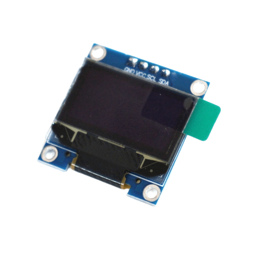
0.96 Inch I2C OLED LCD Module (White, SSD1306)
Add an OLED display to your HC-05 project to show Bluetooth connection status, sensor data, and debug information in real time.
Step 1: Power Supply Verification
Power problems are responsible for at least 30% of HC-05 pairing failures. The HC-05 module requires 3.3V on its VCC pin (the breakout boards with a 6-pin header include a 3.3V regulator and can accept 5V on the VCC pin — but the bare module cannot). Current draw can reach 40mA during active transmission.
Common Power Mistakes
- Powering from Arduino 3.3V pin: The Arduino Uno’s 3.3V regulator is limited to 50mA total. Combined with other 3.3V loads, this causes voltage sag and connection drops. Use a dedicated 3.3V regulator (AMS1117-3.3) for the HC-05 if you are not using a breakout board with an onboard regulator.
- Long jumper wires adding resistance: High-resistance connections cause voltage drop under load. Use short, direct jumper wires.
- Shared GND not connected: The HC-05 and Arduino must share a common GND.
Test: Measure voltage at the HC-05 VCC pin with a multimeter while the module is powered on. It should read 3.3V (±0.1V). If it reads below 3.0V, fix your power supply first.
Step 2: LED Blink Pattern Diagnostics
The HC-05’s onboard LED is your most immediate diagnostic tool:
| LED Pattern | Module State | Action |
|---|---|---|
| Rapid blink (~2/sec) | Data mode, waiting for pairing | Normal — try pairing now |
| Slow blink (~1/sec) | AT Command mode | Send AT commands at 38400 baud |
| Double blink, pause | Paired & connected | Data can now flow |
| LED off | No power / module fault | Check power supply immediately |
| LED steady on | Connected in some configurations | Verify with AT+STATE? |
If you see rapid blinking but your phone cannot find the module, proceed to Step 3 to check AT command settings. If the LED is off despite power, the module may be faulty or you have a wiring error.
Step 3: Enter AT Command Mode & Verify Settings
AT Command mode lets you verify and fix the module’s internal settings. This is the most powerful diagnostic step.
How to Enter AT Mode
- Power OFF the HC-05 and Arduino
- Hold the HC-05’s KEY/EN button (or connect KEY pin to 3.3V/5V)
- Power ON while keeping KEY held
- LED should now blink slowly (~1 per second) — you are in AT mode
- Open Arduino IDE Serial Monitor: set baud to 38400, line ending to Both NL & CR
Essential AT Commands
AT                    → Should reply OK (confirms AT mode is working)
AT+VERSION?           → Returns firmware version (e.g., 3.0-20170601)
AT+NAME?              → Returns module name (default: HC-05)
AT+ADDR?              → Returns Bluetooth MAC address
AT+PSWD?             → Returns current PIN (default: 1234)
AT+UART?             → Returns baud,stopbits,parity (e.g., 9600,0,0)
AT+ROLE?             → Returns role (0=Slave, 1=Master)
AT+STATE?            → Returns current state (INITIALIZED, PAIRABLE, etc.)
Fix Commands
AT+NAME=ZBOTIC_BT     → Rename module (visible in phone Bluetooth scan)
AT+PSWD=1234          → Reset PIN to 1234
AT+UART=9600,0,0      → Set baud rate to 9600 (match your Arduino sketch)
AT+ROLE=0             → Set as Slave (must be 0 for phone-to-Arduino pairing)
AT+RESET              → Restart module in data mode
Critical check: Verify AT+ROLE? returns 0. If the role is 1 (Master), the module will not accept pairing from your phone — it will try to connect TO another device. This is the single most common misconfiguration.
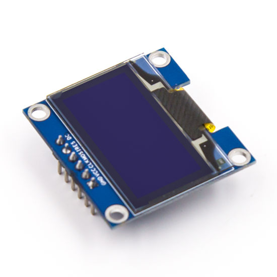
0.96 Inch SPI OLED LCD Module (Blue, SSD1306)
SPI OLED display for showing Bluetooth debug output and sensor readings in Arduino Bluetooth projects.
Step 4: Fix Android Pairing Issues
Android Bluetooth pairing issues with HC-05 are distinct from hardware problems. Here is a reliable procedure:
Standard Android Pairing Procedure
- Make sure HC-05 is in Data Mode (rapid LED blink — NOT AT mode)
- On Android, go to Settings → Connected Devices → Bluetooth
- Tap Scan or Pair new device — you should see "HC-05" (or whatever name you set)
- Tap the device name — you will be prompted for a PIN
- Enter 1234 (or 0000 if 1234 fails)
- Tap OK — the status should change to "Paired"
If HC-05 Does Not Appear in Android Scan
- Toggle Bluetooth OFF and ON on your phone (clears the scan cache)
- Verify HC-05 LED is blinking rapidly (not slow AT mode blink)
- Confirm the HC-05 is not already paired to another device (another phone, laptop) — a paired HC-05 may not be discoverable to additional devices simultaneously
- On newer Android (12+), make sure you have granted "Nearby devices" permission to your Bluetooth app
If Pairing Immediately Fails or Disconnects
- Forget/unpair the device on Android first, then try again fresh
- Reset the HC-05 PIN via AT command:
AT+PSWD=1234 - Some Android 10+ phones have issues with older Bluetooth 2.0 SPP devices — use a dedicated Bluetooth Terminal app (like "Serial Bluetooth Terminal" by Kai Morich) instead of the generic Bluetooth settings pairing
Step 5: Correct Wiring & Voltage Level
Incorrect wiring is another top cause of HC-05 failures. The HC-05’s TX/RX pins operate at 3.3V logic, while Arduino Uno/Nano TX/RX are at 5V logic. Connecting 5V directly to HC-05 RX can damage the module over time.
Correct Wiring (Arduino Uno to HC-05 Breakout Board)
| HC-05 Pin | Arduino Pin | Notes |
|---|---|---|
| VCC | 5V | Breakout boards have onboard 3.3V LDO |
| GND | GND | Common ground — MUST be connected |
| TXD | D10 (SoftSerial RX) | HC-05 sends, Arduino receives — direct OK |
| RXD | D11 (SoftSerial TX) via voltage divider | 5V→3.3V: 1kΩ + 2kΩ resistor divider |
| KEY/EN | D9 (optional) or 3.3V for AT mode | Leave floating for data mode |
Critical: Do NOT connect HC-05 TXD and RXD to Arduino hardware UART pins 0 and 1 while also using USB Serial Monitor — they share the same UART on Uno/Nano and will conflict. Use SoftwareSerial on pins D10/D11 for HC-05.
Step 6: Matching Baud Rate in Code
A mismatch between the HC-05’s configured baud rate and your Arduino sketch’s SoftwareSerial baud rate causes garbled data and apparent "connection" failures where the module pairs but no data flows.
#include <SoftwareSerial.h>

// HC-05 TXD → Arduino D10, HC-05 RXD → Arduino D11 (via voltage divider)
SoftwareSerial bluetooth(10, 11); // RX, TX

void setup() {
  Serial.begin(9600);      // USB Serial Monitor
  bluetooth.begin(9600);   // MUST match AT+UART? setting on HC-05
  Serial.println("HC-05 ready. Waiting for Bluetooth connection...");
}

void loop() {
  // Forward data from Bluetooth to Serial Monitor
  if (bluetooth.available()) {
    char c = bluetooth.read();
    Serial.write(c);
  }

  // Forward data from Serial Monitor to Bluetooth
  if (Serial.available()) {
    char c = Serial.read();
    bluetooth.write(c);
  }
}
This is a transparent bridge sketch — it passes data between your phone’s Bluetooth terminal app and the Arduino Serial Monitor. Use it to verify your HC-05 is working before adding application logic.
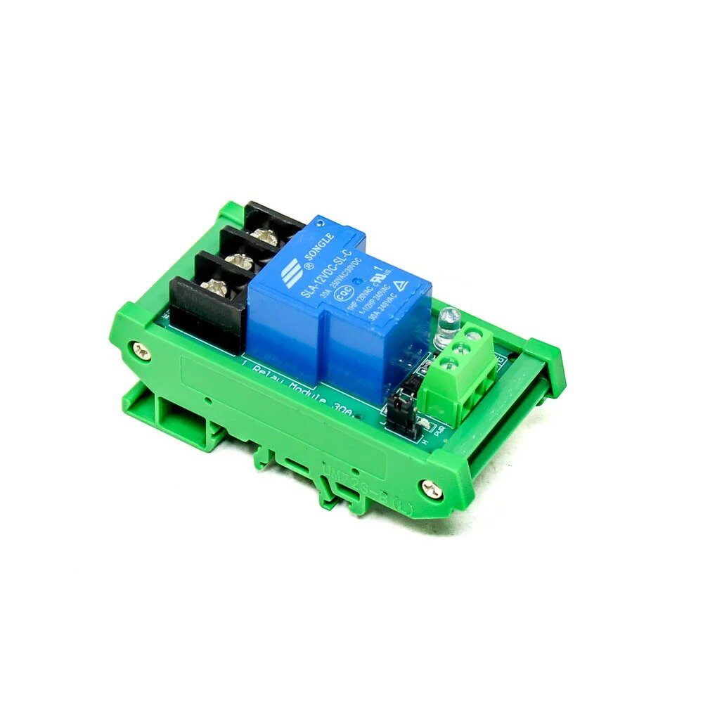
1 Channel 12V 30A Relay Module with Optocoupler
Control high-power devices via Bluetooth using this optocoupler-isolated relay — a natural next step after getting HC-05 working with Arduino.
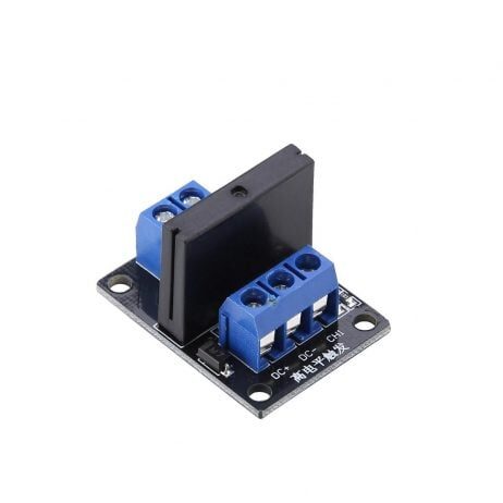
1 Channel 12V Solid State Relay Module (SSR, High Level)
Silent solid-state relay for Bluetooth-controlled AC switching projects — no mechanical noise, longer lifespan than traditional relays.
0.96 Inch SPI OLED LCD Module 7-pin (White, SSD1306)
7-pin SPI OLED display with CS pin — ideal for showing Bluetooth status, commands received, and sensor data in HC-05 Arduino projects.
Frequently Asked Questions
Q: My HC-05 shows in Bluetooth scan but pairing fails immediately. Why?
The most likely cause is a wrong PIN. Try both 1234 and 0000. If both fail, enter AT command mode and run AT+PSWD=1234 to reset the PIN to 1234, then exit AT mode and try pairing again. Also make sure no other device is already connected to your HC-05 — it can only maintain one connection at a time.
Q: Why does AT command mode not respond — my Serial Monitor shows nothing?
Check three things: (1) Baud rate in Serial Monitor must be exactly 38400, not 9600. (2) Line ending in Serial Monitor must be set to “Both NL & CR” — without carriage return, the HC-05 ignores the command. (3) Make sure you entered AT mode correctly (KEY pin HIGH at power-on, slow LED blink). If using SoftwareSerial to communicate with HC-05 in AT mode, note that SoftwareSerial can be unreliable above 9600 on some Arduinos — try connecting the HC-05 directly to hardware UART pins for AT mode testing.
Q: HC-05 pairs successfully but data is garbled or missing. What is wrong?
Baud rate mismatch. The HC-05’s data mode baud rate (check with AT+UART? in AT mode) must exactly match the baud rate you use in bluetooth.begin() in your Arduino sketch. If AT+UART? returns 38400 but your sketch uses 9600, all received data will be garbled. Fix: either change the HC-05 with AT+UART=9600,0,0 or update your sketch to use 38400.
Q: Can HC-05 work with iPhone (iOS)?
No. The HC-05 uses Bluetooth Classic (SPP profile), which iOS does not support for third-party apps. iPhones only support Bluetooth Low Energy (BLE) for custom apps. You need an HC-08, HM-10, or similar BLE module to communicate with iPhone. For Android projects, HC-05 works perfectly.
Q: What is the difference between HC-05 and HC-06? Which is better?
HC-05 supports both Master and Slave modes and has a full AT command set — it can initiate connections as well as accept them. HC-06 is Slave-only with a simplified AT command set (no AT+ROLE command). For most projects where your phone connects to Arduino, HC-06 is simpler and slightly cheaper. HC-05 is better when you need Arduino-to-Arduino Bluetooth communication (one as Master, one as Slave).
Get Your Bluetooth Project Running Today
Zbotic stocks Bluetooth modules, relay boards, OLED displays, and all the components you need for your Arduino wireless control projects — with fast shipping across India.


Add comment