
Galvanic Isolation: Why and How to Isolate Power Rails in Your Circuits
Every experienced electronics designer knows that not all grounds are created equal. When you connect two systems that share a common ground without proper precautions, you risk noise injection, ground loops, and — in the worst case — equipment damage or a safety hazard. Galvanic isolation power rails why how circuit is a topic that comes up repeatedly in industrial control, medical devices, battery management systems, and even in everyday Arduino projects where a microcontroller talks to a high-voltage relay board. This guide explains the concept clearly and shows you how to implement isolation in your own designs.
What Is Galvanic Isolation?
The word galvanic comes from Luigi Galvani, the Italian physicist who first studied electrical stimulation in biological tissue. In electronics, galvanic isolation means that two circuit sections can exchange energy or information without any direct electrical (conductive) path between them. Electrons cannot physically flow from one side to the other.
Instead, energy crosses the boundary through:
- Magnetic fields — transformers and coupled inductors
- Light — optocouplers and optical fibres
- Capacitive coupling — digital isolators like the ISO7241
The result is that the two sides have completely independent ground references. A fault on one side — say, a mains voltage spike — cannot propagate to the other side and damage your microcontroller or, more critically, the person operating the equipment.
Why Is Isolation Needed?
There are three primary reasons to isolate power rails in a circuit design:
1. Safety
The most compelling reason is human safety. If you are measuring voltages on a 230V AC mains circuit with a microcontroller that is also connected to a USB port, a fault can put mains voltage directly on the USB ground — and from there onto any computer or human that touches it. Galvanic isolation creates an impenetrable barrier. This is why medical devices must use isolated power supplies certified to IEC 60601-1, and why motor drives always isolate their gate driver signals from the MCU.
2. Ground Loops and Noise
When two pieces of equipment share a ground path through multiple cables, tiny differences in ground potential create circulating currents — ground loops. These manifest as 50Hz hum in audio equipment, erratic ADC readings in data acquisition systems, and communication errors in RS-485 or CAN networks. Isolation eliminates the shared ground path and therefore eliminates the loop.
3. Voltage Level Translation
Sometimes you need to connect a 3.3V microcontroller to a 24V industrial sensor, or interface a 5V Arduino to a 12V relay board. Instead of a resistor divider (which is fine for low-speed signals), an optocoupler shifts the level cleanly and adds isolation as a bonus.
4. Battery Stack Monitoring
In a multi-cell battery pack, each cell sits at a different absolute voltage — the top cell in a 4S pack is 12.6V above the bottom cell’s negative terminal. A BMS IC monitoring each cell must be isolated from the others, or it will short cells together. This is a classic galvanic isolation use case in every LiPo and EV battery pack.
Methods of Galvanic Isolation
There are four practical isolation technologies available to a hobbyist or engineer:
| Method | Bandwidth | Cost | Best For |
|---|---|---|---|
| Optocoupler | DC – 1 MHz | Very low | Digital signals, relay triggers |
| Transformer (signal) | AC only | Low | Audio, RS-485, CAN |
| Isolated DC-DC | N/A (power) | Medium | Powering isolated circuitry |
| Capacitive isolator IC | Up to 150 Mbps | Medium | SPI, I2C, UART isolation |
In practice, a complete isolated subsystem uses both an isolated DC-DC converter (for power) and an optocoupler or digital isolator IC (for signals). The two pieces work together: the DC-DC feeds the remote circuitry without a conductive connection, and the optocoupler lets the two sides talk without a conductive data path.
Using Optocouplers for Signal Isolation
An optocoupler (also called a photocoupler) contains an LED and a phototransistor in a single package, separated by a transparent insulating layer. The input side drives the LED; the phototransistor on the output side responds to the light. The two sides share no electrical connection — the isolation voltage is typically 2500V to 5000V AC (test voltage, not continuous operating voltage).
Common optocoupler ICs:
- PC817 — ubiquitous, 50kHz bandwidth, sufficient for relay triggering and UART below 9600 baud
- 4N25 / 4N35 — similar to PC817, in through-hole DIP-6
- TLP291 / TLP521 — SMD versions, higher current transfer ratio
- 6N137 — 10 Mbps, ideal for high-speed digital isolation
Basic wiring for an Arduino output to a 12V relay:
- Arduino GPIO → 220Ω resistor → PC817 LED anode (pin 1)
- PC817 LED cathode (pin 2) → Arduino GND
- PC817 collector (pin 4) → 12V via 1kΩ pull-up → Relay coil
- PC817 emitter (pin 3) → 12V GND (isolated)
The Arduino 5V world and the 12V relay world now have zero conductive connection. A fault in the relay circuit cannot reach your microcontroller.
Isolated DC-DC Converters
An optocoupler isolates signals, but you also need isolated power for the remote circuitry. This is where isolated DC-DC converter modules come in. They use a high-frequency transformer internally to transfer power across the isolation barrier.
Popular choices in India:
- B0505S-1W / B0505S-2W — 5V in, 5V out, 1W or 2W, 1500V isolation, SIP-7 package (around ₹30–60)
- B1205S — 12V in, 5V out, 1W
- MEV1D0512SC — dual output ±12V, 1W, useful for op-amp circuits
For a typical BMS or isolated sensor interface, a 1W isolated converter supplies up to 200mA at 5V — enough to power a microcontroller, its I2C sensors, and an OLED display simultaneously.
Design tip: Always add 100nF decoupling capacitors on both input and output of the isolated DC-DC. These modules switch at high frequency (100kHz–1MHz) and can inject noise into sensitive analog circuits without proper decoupling.
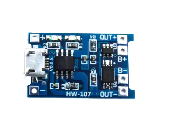
TP4056 1A Li-Ion Battery Charging Board Micro USB with Current Protection
The TP4056 with protection IC is a classic example of isolated power management — the DW01 protection circuit operates across the cell stack with charge/discharge FETs on the negative rail.
Transformer-Based Isolation
For AC signals and power frequencies, a transformer is the oldest and most reliable isolation method. The mains transformer in your wall adapter is a galvanic isolator — 230V AC on the primary, 9V or 12V AC on the secondary, with the two windings separated by a thick insulating bobbin.
In signal applications, small pulse transformers isolate digital data lines in RS-485, Ethernet (the RJ-45 jack you plug into your router contains four isolation transformers!), and CAN bus applications. These operate at frequencies from a few kilohertz up to 100MHz.
For hobbyists, the most accessible transformer isolation is a small 230V:12V mains transformer feeding a bridge rectifier and filter capacitor. This gives a safe, isolated 12V DC rail that can power relay boards, motor drivers, and solenoids without connecting mains potential to your microcontroller ground.
Isolation in Battery Management Systems
Multi-cell BMS designs (4S, 6S, 8S Li-ion packs) face a fundamental challenge: the BMS IC must measure and balance each cell, but cell voltages are stacked. In a 4S pack:
- Cell 1 positive: ~4.2V above pack negative
- Cell 2 positive: ~8.4V above pack negative
- Cell 3 positive: ~12.6V above pack negative
- Cell 4 positive: ~16.8V above pack negative
If a single MCU tries to measure all four cells referenced to pack negative, the ADC inputs of the top cells would see 12–17V — far above any 3.3V MCU’s absolute maximum. The solution is either a dedicated stackable BMS IC (like the BQ76940 with built-in high-voltage level shifters) or isolated measurement per cell.
For DIY packs, the simplest approach is a dedicated BMS module per pack. These modules already include all necessary isolation and protection internally.

1S 12A 3.6V BMS Battery Protection Board for Li-ion Cell
A robust single-cell BMS board rated at 12A continuous. Use one per cell in a DIY multi-cell pack to keep each cell’s protection circuit isolated from the others.

1S 3.7V 2A 1MOS BMS Li-ion 18650 Battery Protection Board
Compact 2A BMS for single 18650 cells. Includes overcharge, over-discharge, and short-circuit protection — the safety net for any isolated battery sub-system.
Frequently Asked Questions
Is galvanic isolation the same as electrical isolation?
They are closely related but not identical. Electrical isolation can refer to any method of preventing current flow, including simply disconnecting a wire. Galvanic isolation specifically means that signal or power can still be transferred (via light, magnetism, or capacitance) but there is no conductive path for DC current between the two domains.
What isolation voltage do I need for a 230V mains application?
Safety standards (IEC 60950, IEC 61010) require at least 1500V RMS isolation for basic insulation and 3000V RMS for reinforced insulation (what you need for equipment that users handle). Most certified optocouplers and isolated DC-DC modules specify 3000–5000V test voltage, which is sufficient for basic insulation in mains-referenced designs.
Can I use a relay instead of an optocoupler?
Yes — a mechanical relay provides complete galvanic isolation between its coil and contacts. However, relays are slow (5–15ms switching), wear out (typically 100,000 operations for mechanical, 10 million for solid-state), and generate contact bounce. Optocouplers are better for high-speed or high-cycle-count applications.
Does using an isolated DC-DC converter eliminate ground loops?
Yes. Once the remote circuit has its own isolated power supply, it has no conductive path to the main system ground, so no circulating loop current can exist. This is the standard fix for ground loop hum in audio equipment and ADC noise in instrumentation.
Are there any downsides to galvanic isolation?
The main drawbacks are cost, board space, and signal bandwidth. Isolated DC-DC converters cost more than linear regulators. Optocouplers have limited bandwidth. Capacitive isolator ICs (the high-speed option) are more expensive and available mainly in SMD packages that are harder to use in hobby prototypes. For applications where isolation is truly necessary, these trade-offs are always worth accepting.
Whether you need BMS protection boards, battery holders, or charging modules, Zbotic.in stocks everything you need to implement proper power rail isolation in your projects. Browse our batteries and power category for a curated selection of components trusted by Indian makers and engineers.


Add comment