
The HB100 microwave Doppler radar module is one of the most capable and least understood motion sensors available to makers and engineers in India. Unlike PIR sensors that detect body heat, or ultrasonic sensors that measure echo time, the HB100 uses the Doppler effect at 10.525 GHz microwave frequency to detect moving objects — regardless of temperature. This makes it suitable for applications in extreme temperatures, through thin walls or plastic enclosures, and where standard sensors fail. In this comprehensive tutorial, you will learn exactly how the HB100 works, how to interface it with Arduino, and how to build practical Doppler radar projects.
How the HB100 Works: The Doppler Principle
The HB100 is a CW (Continuous Wave) Doppler radar module. It transmits a continuous 10.525 GHz microwave signal and receives the reflection from objects in its field of view. When an object is stationary, the reflected signal has the same frequency as the transmitted signal. When an object is moving — toward or away from the sensor — the reflected signal has a slightly different frequency due to the Doppler effect.
The frequency shift (Doppler shift, Δf) is proportional to the object’s velocity relative to the sensor. For a vehicle moving at speed v toward the sensor, the Doppler shift is:
Δf = 2 × v × f₀ / c
Where f₀ = 10.525 GHz and c = speed of light (3×10⁸ m/s). At walking speed (~1.5 m/s), this gives a Doppler shift of around 105 Hz — well within audible and easily measurable frequency range. A car at 50 km/h produces a Doppler shift of about 972 Hz.
The HB100’s internal mixer produces an IF (Intermediate Frequency) output that is the difference between transmitted and received frequencies — exactly the Doppler shift frequency. This IF output is a very small signal (millivolts) that needs amplification before it can be read by a microcontroller.
HB100 Specifications
| Parameter | Value |
|---|---|
| Operating Frequency | 10.525 GHz ± 25 MHz (X-band) |
| Transmit Power | 13–16 dBm EIRP |
| Operating Voltage | 4.75V – 5.25V DC |
| Operating Current | ~60 mA (typical) |
| Detection Range | Up to 20 m (dependent on target and amplification) |
| Beam Angle (H) | ±40° (roughly 80° cone) |
| Beam Angle (V) | ±40° |
| IF Output Signal | 0–5 mV (raw, needs amplification) |
| Doppler Frequency Range | 10 Hz – 10 kHz |
| Operating Temperature | -20°C to +70°C |
| Dimensions | 25 × 25 × 7 mm |
Important note for Indian users: The HB100 operates in the 10.5 GHz X-band. In India, this frequency falls under the unlicensed Short Range Device (SRD) category for indoor industrial sensing applications with limited transmit power. The HB100 at its rated output is compliant for hobbyist and research use. For commercial product deployment, check current WPC India regulations.
HB100 vs PIR vs Ultrasonic: When to Use Which
| Feature | HB100 (Microwave) | PIR Sensor | Ultrasonic (HC-SR04) |
|---|---|---|---|
| Detection Principle | Doppler frequency shift | Infrared heat difference | Echo time-of-flight |
| Detects Non-Living Objects | Yes (any moving object) | No (warm bodies only) | Yes (any solid object) |
| Through Walls/Plastic | Yes (thin non-metallic) | No | No |
| Temperature Immunity | High | Low (affected by heat) | Moderate (sound speed varies) |
| Gives Distance | No (speed only, not distance) | No | Yes |
| False Triggers (wind, heat) | Moderate (fan vibrations) | High (sunlight, heat sources) | Low |
| Circuit Complexity | High (needs amplifier) | Very Low | Low |
| Cost (India) | ₹400–₹700 | ₹30–₹80 | ₹40–₹100 |
Hardware Setup and Pin Description
The HB100 module has 4 pins:
- VCC: 5V supply (use a clean, low-noise 5V regulator — power supply noise couples into the sensitive IF output)
- GND: Ground
- IF+: Positive IF (Intermediate Frequency) output — the Doppler signal
- IF- (or NC): On some modules this is the negative IF or simply not connected. Consult your specific module datasheet.
The raw IF output from the HB100 is typically 0–5 mV amplitude — far too small for an Arduino ADC (which needs 0–5V with useful resolution). You absolutely must amplify this signal before connecting to a microcontroller. The most common approach is a two-stage op-amp circuit using the LM358 or LM324, providing 60–80 dB of voltage gain (1000× to 10000×).
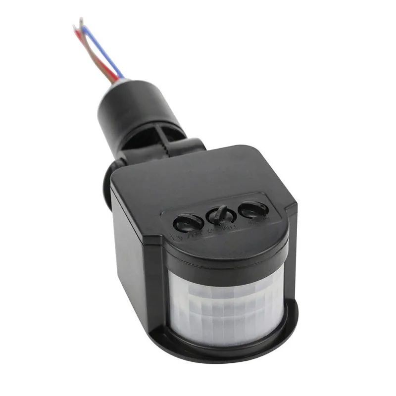
AC 220V PIR Motion Sensor with LED Light Switch
Compare with Doppler radar — this PIR sensor is ideal for indoor human detection where heat-based sensing suffices and simplicity is key.
Signal Conditioning: The Critical Step
The most common reason HB100 projects fail is inadequate signal conditioning. You need a bandpass amplifier — not just a general amplifier — to reliably detect motion.
Two-Stage Amplifier Design
Stage 1 — High-gain amplifier: Use one op-amp section of an LM358 in non-inverting configuration with gain of ~100× (R_feedback = 100 kΩ, R_input = 1 kΩ). Add a 0.1 µF capacitor in series with the input to block DC offset from the HB100 (AC coupling).
Stage 2 — Bandpass filter + additional gain: Second op-amp stage set for gain 100–1000× with RC high-pass filter (cut off below ~10 Hz to reject very slow drift) and RC low-pass filter (cut off above ~5 kHz to reject high-frequency noise). Total system gain of 10,000× (80 dB) converts the 1–5 mV HB100 output to a useful 1–5V signal.
Many Arduino hobbyists use a pre-made HB100 breakout module that already includes the two-stage amplifier circuit. These are available in India and save significant circuit-building effort — the output is a digital HIGH/LOW signal or an analog 0–5V signal depending on the module design.
Arduino Wiring Diagram
If using a pre-built HB100 module with amplifier breakout (recommended):
- Module VCC → Arduino 5V
- Module GND → Arduino GND
- Module OUT (analog) → Arduino A0
- (Some modules also have a digital OUT with adjustable threshold potentiometer → Arduino D2)
Arduino Code: Motion Detection
#define HB100_ANALOG A0
#define HB100_DIGITAL 2

int baseline = 0;
const int MOTION_THRESHOLD = 50; // ADC counts above baseline
const int SAMPLES = 20;

void setup() {
  Serial.begin(9600);
  pinMode(HB100_DIGITAL, INPUT);

  // Calibrate baseline (no motion for 2 seconds)
  Serial.println("Calibrating... keep area clear");
  long sum = 0;
  for (int i = 0; i < SAMPLES; i++) {
    sum += analogRead(HB100_ANALOG);
    delay(100);
  }
  baseline = sum / SAMPLES;
  Serial.print("Baseline: ");
  Serial.println(baseline);
  Serial.println("Radar ready — watching for motion");
}

void loop() {
  int val = analogRead(HB100_ANALOG);
  int deviation = abs(val - baseline);

  if (deviation > MOTION_THRESHOLD) {
    Serial.print("MOTION DETECTED! Signal: ");
    Serial.println(val);
    delay(500); // debounce
  }

  // Also check digital output if available
  if (digitalRead(HB100_DIGITAL) == HIGH) {
    Serial.println("Digital trigger: MOTION");
  }

  delay(20);
}
Speed Measurement with HB100
By measuring the frequency of the Doppler IF signal, you can calculate the velocity of the detected object. Using FFT (Fast Fourier Transform) on samples of the amplified IF signal gives you the dominant frequency component, which you can convert to speed using the Doppler formula.
// Speed calculation from Doppler frequency
// For HB100: f₀ = 10.525 GHz, c = 3×10⁸ m/s
// v (m/s) = (Δf × c) / (2 × f₀)
// v (km/h) = v (m/s) × 3.6

float dopplerFreqToSpeed(float freqHz) {
  float c = 3e8;          // Speed of light
  float f0 = 10.525e9;    // HB100 transmit frequency
  float velocity_ms = (freqHz * c) / (2.0 * f0);
  return velocity_ms * 3.6; // Convert to km/h
}

// Example: 100 Hz Doppler → speed
void setup() {
  Serial.begin(9600);
  float speed = dopplerFreqToSpeed(100.0);
  Serial.print("100 Hz Doppler = ");
  Serial.print(speed);
  Serial.println(" km/h");
  // Output: ~10.2 km/h (walking speed)
}
Full FFT implementation requires the ArduinoFFT library and sampling the ADC at a known rate (at least 2× the maximum Doppler frequency you want to detect). For vehicle speed detection (up to ~200 km/h), sample at ≥4 kHz and compute FFT on 256-sample windows.
Reducing False Triggers: Tips and Tricks
- Stable 5V supply: Use a low-noise LDO regulator (like AMS1117-5.0) dedicated to the HB100. Shared power rails with motors or relays cause interference.
- Ground plane: Mount the HB100 on a PCB with a solid ground plane beneath the module to reduce EMI pickup.
- Vibration isolation: Fans, compressors, and other vibrating mechanical equipment near the sensor cause periodic IF signals at the vibration frequency. Filter these with a narrowband pass filter or software threshold duration checking (require motion signal to persist for >200 ms).
- Software debouncing: Require the motion signal to exceed threshold for N consecutive samples before declaring motion detected. This eliminates single-sample spikes.
- Orientation: The HB100 is most sensitive when the target moves directly toward or away from the sensor. Objects moving perpendicular to the beam axis produce a much lower Doppler shift — useful for focusing detection on specific directions.
- Bandwidth limiting: If you only want to detect walking humans (Doppler 40–300 Hz), add a narrow bandpass filter. This rejects both slow structural vibrations and fast electrical noise.

B2X2 4-Element Analog PIR Sensor for Lighting
For temperature-stable indoor environments where cost matters, this 4-element analog PIR offers high sensitivity with easy mains integration.
Project Ideas and Applications
- Vehicle speed gun: Mount the HB100 pointing down a road. With FFT analysis on ESP32 or Arduino + FFT shield, display vehicle speed on an OLED — great for science fairs and traffic monitoring demos.
- Security alarm through plastic enclosure: Install the HB100 inside an IP65 plastic junction box. Microwaves penetrate plastic but not metal. Detect intruders without an exposed sensor surface.
- Automatic door opener: Place HB100 above a doorway. Detect approaching persons and trigger a door motor or electric bolt solenoid. Unlike PIR, this works in hot climates where body temperature approaches ambient temperature.
- Industrial conveyor speed monitor: Detect belt or product speed in a factory environment where PIR or ultrasonic would be unreliable due to temperature, dust, or reflective surfaces.
- Sleep monitor (non-contact): Place the HB100 above a bed. Breathing and movement produce subtle Doppler signals — with FFT analysis you can detect respiratory rate and sleep movement patterns.
- Smart parking sensor: Detect vehicles entering/leaving a parking bay using microwave — reliable in rain, dust, and harsh outdoor conditions.
JSN-SR04T Waterproof Ultrasonic Rangefinder Module
Where HB100 gives speed, the JSN-SR04T gives precise distance — combine both sensors for a complete vehicle detection and ranging system.
Frequently Asked Questions
Is the HB100 safe to use indoors?
Yes. The HB100 transmits at approximately 13–16 dBm EIRP, which is extremely low power — comparable to a Wi-Fi router or microwave oven’s standing wave at a distance. At operational distances of 1–10 m, the power density is well below any safety threshold. Extended exposure at operating ranges poses no known health risk.
Can the HB100 detect motion through walls?
The 10.525 GHz signal penetrates thin non-metallic materials including plastic housings, plywood, drywall (no metal backing), and thin glass. Reinforced concrete, brick, and any metal surfaces will block or attenuate the signal significantly. Practical through-wall detection range is 1–3 m depending on wall material and thickness.
Why is my HB100 triggering randomly with no motion present?
Common causes: (1) Power supply noise coupling into the sensitive IF output — use a dedicated low-noise regulator. (2) Vibrating mechanical equipment in range (fans, compressors) — software debouncing helps. (3) Fluorescent light ballasts — these can produce 50 Hz or 100 Hz interference that looks like a slow motion signal. (4) The amplifier circuit is picking up 50 Hz mains hum — ensure proper shielding and short IF output traces.
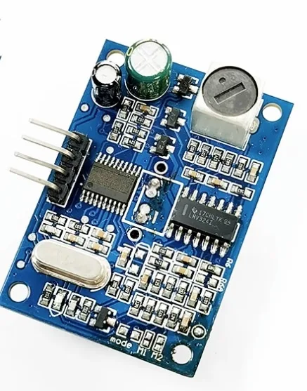
What is the difference between the HB100 and RCWL-0516?
The RCWL-0516 is a cheaper microwave Doppler module (~₹40–80 in India) that operates at ~3.18 GHz with all signal processing integrated — it outputs a direct digital HIGH/LOW. The HB100 operates at 10.525 GHz (better directivity, less interference from household electronics), has higher sensitivity and range, provides an analog IF output for speed measurement, but requires an external amplifier. RCWL-0516 is simpler to use; HB100 is more capable.
Can I use the HB100 with a Raspberry Pi?
Yes, through the amplified IF signal. Connect the amplifier output to the Raspberry Pi’s ADC (you need an external ADC like MCP3008 since Pi has no built-in ADC, or use the Pi’s UART if you add a comparator to get digital output). The Pi’s processing power is ideal for FFT-based speed calculations in Python using NumPy.
From microwave Doppler radar to PIR sensors and ultrasonic rangefinders, Zbotic has the complete range. Explore all sensor modules at Zbotic.in — quality components, fast delivery across India.


Add comment