
Table of Contents
- What Is the TTP223 Capacitive Touch Sensor?
- How Capacitive Touch Sensing Works
- TTP223 Pinout and Technical Specifications
- Operating Modes: Toggle vs Momentary
- Wiring the TTP223 to Arduino
- Basic Arduino Code: Reading Touch Input
- Project 1: Touch-Controlled LED
- Project 2: Touch-Activated Relay Switch
- Expanding to Multi-Touch Pads
- Troubleshooting Common Issues
- Real-World Applications
- Frequently Asked Questions
Mechanical push buttons are robust and reliable, but they wear out over time, collect dust, and require actual physical pressure. Capacitive touch sensors solve all three problems. The TTP223 capacitive touch sensor module is one of the most popular single-pad touch ICs in the hobbyist and prototyping world — it is affordable, easy to use, and works flawlessly with Arduino, ESP8266, ESP32, and virtually any microcontroller that can read a digital GPIO pin.
In this comprehensive guide, you will learn exactly how the TTP223 works, how to wire it, how to configure its two operating modes, and how to build two complete projects from scratch. Whether you are building a sleek lamp controller, a touch keypad, or an IoT appliance, this tutorial covers everything you need.
What Is the TTP223 Capacitive Touch Sensor?
The TTP223 is a single-key capacitive touch pad detector IC manufactured by Tontek Design Technology. It is available as a bare IC in SOT-23-6 packaging, but hobbyists almost universally use it in its pre-soldered module form: a small PCB (roughly 24 mm × 24 mm) with an exposed copper touch pad on top, three header pins on the side, and the TTP223 IC plus decoupling capacitors already assembled.
The module detects a human finger touching the copper pad by measuring tiny changes in capacitance. When your finger gets close to the pad, it forms a small capacitor with the electrode. The TTP223 IC measures this capacitance shift and outputs a digital HIGH or LOW signal on its output pin. No analog reading is required — just a simple digital GPIO on your microcontroller.
Key advantages of the TTP223 over mechanical buttons:
- No moving parts — effectively unlimited lifespan
- Works through glass, acrylic, or thin plastic overlays (up to ~6 mm)
- Very low power standby current (about 1.5 µA)
- Fast response time (~60 ms typical)
- Simple 3-pin interface (VCC, GND, SIG)
- Configurable as toggle (latching) or momentary output
How Capacitive Touch Sensing Works
To appreciate what the TTP223 does internally, it helps to understand capacitive sensing basics. A capacitor stores charge between two conductive plates separated by an insulator. The human body is conductive, and when a finger comes near a metal electrode, it acts as one plate of a capacitor with the electrode as the other plate.
The TTP223 uses a technique called charge transfer sensing. The IC repeatedly charges the electrode pad to a reference voltage and then measures how long it takes to discharge through a known resistor. When no finger is present, the small natural capacitance of the pad causes it to discharge in a predictable time. When a finger is nearby, the added capacitance slows the discharge. The TTP223 compares this timing against a calibrated baseline and, when the difference exceeds a threshold, triggers its output.
The IC performs automatic calibration: it continuously updates its baseline to compensate for environmental changes like humidity, temperature, and contamination on the pad. This means the sensor remains reliable even in changing conditions, and you do not need to recalibrate it manually.
TTP223 Pinout and Technical Specifications
The standard TTP223 module has three pins:
| Pin | Label | Description |
|---|---|---|
| 1 | VCC | Power supply: 2.0 V to 5.5 V |
| 2 | SIG / OUT | Digital output (active HIGH by default) |
| 3 | GND | Ground |
Technical specifications at a glance:
- Operating voltage: 2.0 V – 5.5 V (works at both 3.3 V and 5 V logic)
- Standby current: ~1.5 µA (low power mode)
- Operating current: ~3.5 µA
- Response time: 60 ms (fast) / 220 ms (low power)
- Output type: CMOS push-pull, can source/sink up to 8 mA
- Operating temperature: −40 °C to +85 °C
- Sensing area: ~8 mm² (the copper pad on the module)
Two small solder pad jumpers on the back of the module — labeled A and B — configure the operating mode and output polarity. More on those in the next section.
Operating Modes: Toggle vs Momentary
The TTP223 module can be configured via two solder pads on the PCB back:
Pad A — Output polarity:
- A open (default): Output is active HIGH — goes HIGH when touched, LOW when not touched
- A bridged: Output is active LOW — goes LOW when touched, HIGH when not touched
Pad B — Operating mode:
- B open (default): Momentary mode — output follows touch state in real time. Output is HIGH only while finger is on the pad.
- B bridged: Toggle (latch) mode — each touch toggles the output. First touch → HIGH, second touch → LOW, and so on. This is like a push-on/push-off button.
For an LED toggle lamp, bridge pad B so each touch flips the light on or off. For a doorbell or alarm trigger that should only fire while pressed, leave pad B open for momentary mode. You bridge the pads by adding a small blob of solder across the two exposed copper areas.
Wiring the TTP223 to Arduino
The wiring is extremely simple. You need only three wires:
| TTP223 Pin | Arduino Pin |
|---|---|
| VCC | 5 V (or 3.3 V for ESP8266/ESP32) |
| GND | GND |
| SIG | Digital Pin 7 (or any GPIO) |
No pull-up or pull-down resistors are needed. The TTP223 output is a strong push-pull CMOS driver that firmly pulls the line HIGH or LOW. Connect the SIG pin directly to your Arduino digital input.
Important note for 3.3 V boards (ESP8266, ESP32, Arduino Due): The TTP223 accepts 3.3 V supply and its output will swing to 3.3 V, which is compatible with 3.3 V logic GPIO pins. Simply connect VCC to the 3.3 V rail instead of 5 V.
Basic Arduino Code: Reading Touch Input
Here is the minimal sketch to read the TTP223 and print its state to the Serial Monitor:
const int TOUCH_PIN = 7;

void setup() {
  Serial.begin(9600);
  pinMode(TOUCH_PIN, INPUT);
  Serial.println("TTP223 Touch Sensor Ready");
}

void loop() {
  int touchState = digitalRead(TOUCH_PIN);

  if (touchState == HIGH) {
    Serial.println("TOUCHED");
  } else {
    Serial.println("Not touched");
  }

  delay(200);
}
Upload this sketch, open the Serial Monitor at 9600 baud, and touch the copper pad. You will see “TOUCHED” print to the console. Remove your finger and it immediately returns to “Not touched”. This confirms the sensor is wired and working correctly before you proceed to a full project.
Project 1: Touch-Controlled LED
This first project builds a touch lamp: a single touch turns the LED on, the next touch turns it off. This is the classic “toggle” use case.
Components needed:
- Arduino Uno (or Nano)
- TTP223 capacitive touch sensor module (pad B bridged for toggle mode)
- 5 mm LED (any colour)
- 220 Ω resistor
- Jumper wires and breadboard
Wiring:
- TTP223 VCC → Arduino 5 V
- TTP223 GND → Arduino GND
- TTP223 SIG → Arduino Pin 7
- Arduino Pin 13 → 220 Ω resistor → LED anode → LED cathode → GND
Code:
const int TOUCH_PIN = 7;
const int LED_PIN   = 13;

void setup() {
  pinMode(TOUCH_PIN, INPUT);
  pinMode(LED_PIN, OUTPUT);
}

void loop() {
  int touchState = digitalRead(TOUCH_PIN);
  // In toggle mode, the TTP223 output directly reflects the latch state
  digitalWrite(LED_PIN, touchState);
}
Because pad B is bridged (toggle mode), the TTP223 handles the latching internally. You do not need to track state in your code — the sensor’s output IS the state. Each touch flips the output, and your LED mirrors it instantly. This is one of the great conveniences of the TTP223: toggle logic is handled in hardware.
If you prefer software toggle (keeping pad B open, momentary mode), use this approach instead:
const int TOUCH_PIN = 7;
const int LED_PIN   = 13;

bool ledState = false;
bool lastTouch = false;

void setup() {
  pinMode(TOUCH_PIN, INPUT);
  pinMode(LED_PIN, OUTPUT);
}

void loop() {
  bool currentTouch = digitalRead(TOUCH_PIN);

  // Detect rising edge (finger just placed)
  if (currentTouch && !lastTouch) {
    ledState = !ledState;
    digitalWrite(LED_PIN, ledState);
  }

  lastTouch = currentTouch;
  delay(50);
}
Project 2: Touch-Activated Relay Switch
For controlling mains-voltage devices (lamps, fans, appliances), you need a relay. This project connects the TTP223 to a 5 V relay module to switch a 230 V AC load safely.
Additional components:
- 5 V single-channel relay module (with optocoupler isolation)
- AC load (lamp or fan) — handle with care, mains voltage is dangerous
Wiring:
- TTP223 SIG → Arduino Pin 7
- Arduino Pin 8 → Relay module IN pin
- Relay module VCC → Arduino 5 V
- Relay module GND → Arduino GND
- AC load connected via relay’s COM and NO (normally open) terminals
Code (software toggle, momentary TTP223 mode):
const int TOUCH_PIN = 7;
const int RELAY_PIN = 8;

bool relayState = false;
bool lastTouch  = false;
unsigned long lastDebounce = 0;
const unsigned long DEBOUNCE_MS = 100;

void setup() {
  pinMode(TOUCH_PIN, INPUT);
  pinMode(RELAY_PIN, OUTPUT);
  digitalWrite(RELAY_PIN, LOW); // relay off at start
}

void loop() {
  bool currentTouch = digitalRead(TOUCH_PIN);
  unsigned long now  = millis();

  if (currentTouch && !lastTouch && (now - lastDebounce > DEBOUNCE_MS)) {
    relayState = !relayState;
    digitalWrite(RELAY_PIN, relayState ? HIGH : LOW);
    lastDebounce = now;
  }

  lastTouch = currentTouch;
}
A 100 ms debounce window prevents accidental double-toggles if the capacitive pad briefly bounces between detected/not-detected states during a finger lift. This is especially important at mains voltage where unintended toggling could be hazardous.
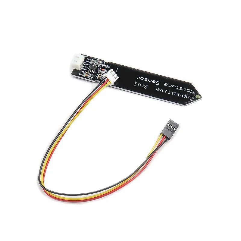
Capacitive Soil Moisture Sensor
Uses the same capacitive sensing principle as the TTP223 — ideal for learning and plant automation projects.

LM35 Temperature Sensors
Combine with your TTP223 touch project to build a touch-activated temperature display system.
Expanding to Multi-Touch Pads
One TTP223 module gives you one touch button. But many projects need multiple buttons — think volume up/down, menu navigation, or a 4-button control panel. You have two options:
Option 1: Multiple TTP223 modules
Simply use one module per button. Each SIG pin connects to a separate Arduino GPIO. This is the easiest approach and works well for 2–6 buttons. The modules are small enough to fit on a standard breadboard without crowding.
Option 2: TTP226/TTP229 ICs
For 8 or 16 touch keys from a single IC, look at the TTP226 (8-key, SPI interface) or TTP229 (16-key, 2-wire serial). These share the same TTP-family design philosophy but communicate via serial interfaces, saving GPIO pins significantly.
Custom touch pads: You are not limited to the onboard copper pad. The TTP223 IC has an electrode pin (pin 1 on the SOT-23 package) that you can wire to any conductive surface — a strip of copper tape, a coin soldered to a wire, or a metal button cap. This lets you build embedded touch surfaces inside custom enclosures, sensing through plastic or wood up to 6 mm thick.
Troubleshooting Common Issues
Sensor always reads HIGH (falsely triggered):
- Check for floating wires near the sensor pad — stray capacitance can trigger detection
- Make sure GND is connected and solid; a floating GND will cause erratic behaviour
- Keep the sensor away from large metal surfaces which can interfere with calibration
Sensor never triggers:
- Verify VCC is actually 3.3 V or 5 V with a multimeter
- Check that SIG is read as INPUT, not OUTPUT
- Try touching with more of your fingertip — covering more of the pad area increases signal
Sensor triggers but output never stays on (toggle not working):
- Confirm pad B is bridged with solder, not just a visual mark
- Power-cycle the module after bridging the pad — the IC resets its mode on power-up
Works in air but not through enclosure:
- Capacitive sensing works through up to ~6 mm of non-conductive material
- Reduce enclosure wall thickness, or move the module closer to the surface
- Avoid metallic paints or conductive coatings on the overlay
Real-World Applications
The TTP223 shows up in an impressive variety of real products and DIY builds:
- Smart lamps and dimmers: Touch-on/off bedside lamps, desk lights with multi-zone touch areas for brightness control
- Kitchen appliances: Induction cooktops, microwaves, and ovens use capacitive touch panels for hygienic, easy-to-clean control surfaces
- IoT devices: Touch wake-up buttons on ESP8266 or ESP32-based smart home controllers
- Wearables and costume props: Conductive fabric touch sensors wired to a TTP223 for gesture-activated LED costumes
- Security panels: Hidden touch spots in furniture that trigger alarms or unlock mechanisms
- Assistive technology: Large-area touch pads for users with limited fine motor control, replacing small buttons
- Industrial panels: Sealed front panels with no holes or cracks — the touch surface is laminated behind glass for dust and water resistance
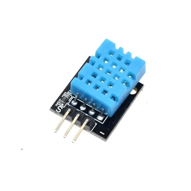
DHT11 Temperature and Humidity Sensor Module
Add environmental sensing to your touch-button project — read temperature and humidity with a single digital pin.
Frequently Asked Questions
Does the TTP223 work with gloves on?
Standard latex or nitrile gloves are thin enough that capacitive sensing still works — the glove simply increases the effective dielectric between your finger and the pad, slightly reducing sensitivity. Thick rubber gloves or heavily insulated work gloves will block the signal. A stylus with a conductive tip will also work.
Can I use the TTP223 underwater?
Not directly — water is conductive and will permanently trigger the sensor. However, if the sensor is sealed behind a waterproof barrier (like a silicone membrane or polycarbonate panel), it can work in wet environments because the sensing is done through the barrier without contact with water.
Does the TTP223 work with 3.3 V (ESP8266, ESP32)?
Yes. The TTP223 operates from 2.0 V to 5.5 V. At 3.3 V supply, its output swings between 0 V and 3.3 V, which is perfectly compatible with 3.3 V logic microcontrollers. No level shifter is needed.
How do I increase the sensing distance?
The default sensing distance is the size of the onboard copper pad at contact range. To increase it, attach a larger copper plate to the electrode pad — area and distance to the human finger have a direct relationship with capacitance change. Some builders use 5 cm × 5 cm copper tape electrodes to allow detection through thick panels.
Can multiple TTP223 sensors interfere with each other?
If the copper pads are spaced more than ~2–3 cm apart, interference is negligible. If you pack them very closely (under 1 cm between pads), you may get cross-talk where touching one pad also triggers adjacent sensors. For close-packed arrays, the TTP226/TTP229 ICs handle inter-electrode compensation internally.
What is the difference between TTP223 and TTP223B?
The TTP223B is the standard version most modules use. The B suffix indicates the specific pin-out variant in the SOT-23 package. There are also TTP223-BA6 and TTP223-BOA6 variants which differ in output polarity defaults and package style, but for practical module use they are functionally equivalent and the differences are handled by the A/B solder pads on the module PCB.
Conclusion
The TTP223 capacitive touch sensor is a genuinely excellent component for any electronics project. Its simplicity — three pins, no resistors, immediate digital output — makes it accessible to beginners, while its configurable modes, wide voltage range, and ability to sense through materials make it useful in professional product designs. With toggle mode enabled (pad B bridged), it replaces a latching push button without a single moving part. With momentary mode, it provides clean debounce-free input for counters, menu navigation, or wake-up triggers.
The two projects in this guide — the touch-controlled LED and the touch-activated relay — cover the most common use cases. From here, you can extend to multi-pad arrays, build custom electrodes for hidden touch spots, or integrate the TTP223 with WiFi-enabled microcontrollers for smart home applications. The sensor is available individually or in packs, and at its price point, it is worth keeping a handful in your components drawer at all times.


Add comment