
One of the most common wiring headaches in electronics projects is the voltage mismatch between 5V microcontrollers (Arduino Uno, Nano, Mega) and 3.3V sensors and modules (ESP32, Raspberry Pi, most modern sensor ICs). Connecting a 3.3V sensor directly to a 5V signal pin can permanently damage the sensor. Connecting a 5V device’s output to a 3.3V microcontroller without protection can destroy the ADC input. A bidirectional logic level shifter solves this problem elegantly and safely.
This comprehensive tutorial explains the theory behind level shifting, covers all the different circuit approaches, helps you choose the right module for I2C, SPI, UART, and GPIO applications, and walks through practical wiring examples for the most common Arduino + sensor combinations.
Why Level Shifting Is Necessary
Modern electronics has bifurcated into two dominant logic voltage families: 5V TTL/CMOS (legacy Arduino, older AVR, PIC microcontrollers) and 3.3V CMOS (ESP32, ESP8266, STM32, Raspberry Pi, and virtually all modern sensor ICs released after 2010). These two families have different voltage thresholds:
| Voltage Level | Logic HIGH | Logic LOW | Max Input Voltage |
|---|---|---|---|
| 5V TTL (Arduino Uno) | > 2.4V | < 0.8V | 5.5V |
| 3.3V CMOS (ESP32) | > 2.0V | < 0.8V | 3.6V |
| 3.3V Sensor IC (typical) | > 1.8V or > 0.7 × VDD | < 0.5V | VDD + 0.3V (≈3.6V) |
The critical number is Max Input Voltage. Most 3.3V sensors have an absolute maximum input voltage of VDD + 0.3V = 3.6V. Applying a 5V HIGH signal from an Arduino directly to such a pin applies 5V to a 3.6V-maximum input. This exceeds the absolute maximum rating and causes permanent damage — often not immediately, but through progressive oxide breakdown that kills the device within hours, days, or weeks.
Conversely, a 3.3V HIGH output from a sensor or ESP32 is correctly interpreted as HIGH by a 5V Arduino input (since Arduino’s HIGH threshold is 2.4V and 3.3V > 2.4V). So the low-to-high direction is often safe without a level shifter — but the high-to-low direction (5V Arduino output to 3.3V device input) always requires protection.
Bidirectional level shifters handle both directions automatically, making them safe and straightforward for use with protocols like I2C and SPI where the same wire carries data in both directions.
Types of Level Shifters
Several distinct circuit techniques exist for logic level conversion:
1. Resistor Voltage Divider (Unidirectional, High to Low only)
The simplest possible approach: two resistors form a divider that reduces 5V to 3.3V. A common ratio is 10 kΩ (top) + 20 kΩ (bottom), producing exactly 3.33V output when input is 5V.
Limitation: Works only one way (5V → 3.3V). Cannot work for bidirectional protocols like I2C. Slow — the RC time constant from resistors and wire capacitance limits bandwidth to a few hundred kHz at best. Adequate only for slow analog signals or very slow digital signals.
2. Zener Diode Clamp (Unidirectional, crude)
A 3.3V Zener diode placed between the signal and GND clamps the voltage to 3.3V. Better than nothing, but not a proper logic level converter — the Zener’s forward voltage tolerance means it doesn’t produce a clean HIGH/LOW transition.
3. BSS138 N-MOSFET Bidirectional Shifter (Recommended for I2C/GPIO)
The best general-purpose bidirectional level shifter for I2C and slow SPI. Uses a single N-channel MOSFET (BSS138, 2N7002, or similar) with body diode for automatic bidirectionality. This is what SparkFun’s popular BOB-12009 level shifter module uses. Full explanation in the next section.
4. Dedicated Level Shifter ICs
- TXB0108: 8-channel bidirectional level translator from Texas Instruments. Suitable for SPI and GPIO. NOT suitable for I2C (output enable pull-up of I2C conflicts with TXB0108’s push-pull output).
- TXS0102/TXS0108: Similar to TXB0108 but with better I2C compatibility (open-drain mode). Handles up to 110 Mbps.
- PCA9306: Specifically designed for I2C and SMBus voltage translation. Handles 100 kHz and 400 kHz I2C speeds reliably. Best choice for I2C-heavy designs.
- 74LVC1T45: 1-bit unidirectional level shifter. Use two for a bidirectional channel. Very fast (100+ MHz) — suitable for SPI at high clock rates.
The BSS138 MOSFET Bidirectional Level Shifter
Understanding this circuit is worth your time — it appears in thousands of Arduino-sensor interface designs worldwide.
HV (5V) ─────[10kΩ pull-up]─────── HV Side Signal
                                          │
                                     Gate (G)
                                     │
LV (3.3V) ──[4.7kΩ pull-up]─ Drain (D) [BSS138]
                                     │
                               Source (S)
                                     │
                                    GND
How it works in both directions:
Low → High (LV device pulls line low): When the 3.3V device drives the LV signal line LOW (0V), the MOSFET’s gate (connected to LV line) sees 0V. Gate-to-source voltage (Vgs) = 0V − 0V = 0V… wait. The source is connected to LV side at 0V (LOW). Actually: Source = 0V, Gate = 0V, Vgs = 0V, MOSFET turns off. The HV side is pulled low through the MOSFET’s body diode and the 5V → LV conduction path: the diode allows current to flow from HV to source, which then equalises to approximately 0V, pulling the HV line low as well. The 10 kΩ pull-up on the HV side cannot overcome this — the HV line goes LOW. When the LV side releases (goes HIGH via 4.7 kΩ pull-up), Vgs rises, the MOSFET turns on, and both sides equalise to LV HIGH (3.3V).
High → Low (HV device pulls line low): When the 5V device pulls the HV line to 0V, the gate (connected to LV side via 4.7 kΩ to 3.3V) now has Vgs = 3.3V − 0V = 3.3V > Vth (≈1V for BSS138). MOSFET turns on, pulling the LV side LOW as well. When HV releases, MOSFET gate drops, MOSFET turns off, LV side pulled HIGH by 4.7 kΩ to 3.3V.
This elegant circuit works because the MOSFET and its body diode together create a path in both directions for the signal to propagate. The asymmetry in pull-up values (4.7 kΩ LV vs 10 kΩ HV) is intentional — optimise based on capacitive load and speed requirements.
Level Shifting for I2C
I2C is the most common protocol to level-shift because:
- It’s bidirectional on a single wire (SDA)
- It’s open-drain — devices can only pull the line LOW, never actively drive it HIGH
- Multiple devices share the same bus
The BSS138 circuit is perfect for I2C. For each wire (SDA and SCL), you need one MOSFET channel. Most level shifter breakout boards have 4 channels — you use 2 for I2C and have 2 spare for other signals.
Correct pull-up resistor values for I2C level shifting:
- Remove or disable pull-ups on both device sides if your breakout boards have them built in
- Place 4.7 kΩ pull-ups on LV side (3.3V → SDA_LV and SCL_LV)
- Place 10 kΩ pull-ups on HV side (5V → SDA_HV and SCL_HV)
- For fast I2C (400 kHz), reduce to 2.2 kΩ (LV) and 4.7 kΩ (HV)
The PCA9306 is the cleanest dedicated solution for I2C level shifting in production designs. It’s available in breakout form from SparkFun and works with both 100 kHz and 400 kHz I2C without any external components beyond the IC itself.
Level Shifting for SPI
SPI has four lines: MOSI (master out), MISO (master in), SCK (clock), and CS (chip select). All four need level shifting. Unlike I2C, SPI uses push-pull outputs — devices actively drive both HIGH and LOW.
The BSS138 circuit works for SPI at speeds up to ~1 MHz. Above that, propagation delay through the MOSFET circuit accumulates, causing timing issues. For high-speed SPI:
- 1–10 MHz: Use TXS0108 (bi-directional, 8-channel, handles 30 Mbps). Note MISO direction is reversed from MOSI/SCK/CS perspective — TXS0108 auto-senses direction.
- 10–50 MHz: Use 74LVC1T45 per signal, with direction set by a control pin (since you know which signals are MCU→sensor vs. sensor→MCU for SPI).
Level Shifting for UART/Serial
UART (TX/RX) is unidirectional — TX from one device goes to RX on the other and vice versa. This simplicity makes level shifting easier.
For 5V Arduino UART TX → 3.3V device RX:
- A simple resistor divider works (10 kΩ + 20 kΩ) since UART signals are unidirectional and relatively slow (115200 baud = 8.68 μs per bit, much slower than the RC time constant of a voltage divider)
- Or use one channel of a BSS138 level shifter module
For 3.3V device UART TX → 5V Arduino RX:
- No level shifting required! Arduino’s TTL input accepts 3.3V HIGH as logic HIGH. Direct connection is safe.
Simple GPIO Level Shifting
For single GPIO pins (not protocols), the options expand:
- Resistor divider: Adequate for slow digital inputs (buttons, slow sensor outputs). Use 2.2 kΩ + 3.3 kΩ for 5V → 3.3V with low impedance output, or 10 kΩ + 20 kΩ for high-impedance sources.
- Single BSS138 channel: Best for any digital output with switching speeds above a few kHz.
- Optocoupler: Not a level shifter per se, but provides galvanic isolation. Useful when ground potentials differ between circuits (motor driver outputs, mains-referenced signals).
Popular Level Shifter Modules Compared
| Module | Channels | I2C | SPI | Max Speed |
|---|---|---|---|---|
| SparkFun BOB-12009 (BSS138) | 4 | Yes | Slow | ~1 MHz |
| Generic 4-Channel (BSS138) | 4 | Yes | Slow | ~1 MHz |
| TXS0108E Module (8-ch) | 8 | Partial | Yes | 30 Mbps |
| PCA9306 Module (I2C only) | 2 (I2C) | Best | No | 400 kHz |
| Resistor Divider (DIY) | Per resistor set | No | No | <100 kHz |
For 95% of Arduino hobbyist projects, the generic 4-channel BSS138 module (₹30–80 on Indian electronics marketplaces) is the right choice. It handles I2C, slow SPI, UART, and GPIO signals for any combination of 5V and 3.3V devices.
Wiring: Arduino 5V + ESP32 3.3V via Level Shifter
A common scenario: using an Arduino Uno as the main controller with an ESP32 as a Wi-Fi co-processor, communicating over UART or SPI.
UART Communication (Arduino TX → ESP32 RX)
| Level Shifter Pin | Connect To |
|---|---|
| HV | Arduino 5V |
| LV | ESP32 3.3V |
| GND | Common GND (both boards) |
| HV1 (TX in) | Arduino TX (pin 1) |
| LV1 (TX out) | ESP32 RX (GPIO3) |
| LV2 (RX in) | ESP32 TX (GPIO1) — direct to Arduino is safe, but use shifter for symmetry |
| HV2 (RX out) | Arduino RX (pin 0) |
Wiring: Arduino + 3.3V Sensor Modules
Let’s walk through connecting an Arduino Uno (5V) to a BME280 pressure/temperature/humidity sensor (3.3V) via I2C using a level shifter.
Components:
- Arduino Uno
- BME280 sensor module (3.3V version)
- 4-channel BSS138 bidirectional level shifter
Arduino Uno → Level Shifter → BME280

5V     → HV
GND    → GND
A4(SDA)→ HV-SDA → LV-SDA → BME280 SDA
A5(SCL)→ HV-SCL → LV-SCL → BME280 SCL
              LV  → BME280 VCC (3.3V)
              GND → BME280 GND
In Arduino code, use the standard Wire library and BME280 library — the level shifter is completely transparent to the software:
#include <Wire.h>
#include <Adafruit_BME280.h>

Adafruit_BME280 bme;

void setup() {
  Serial.begin(9600);
  Wire.begin(); // Uses Arduino's A4/A5

  if (!bme.begin(0x76)) {
    Serial.println("BME280 not found! Check level shifter wiring.");
    while (1);
  }
  Serial.println("BME280 connected via level shifter.");
}

void loop() {
  Serial.print("Temperature: "); Serial.print(bme.readTemperature()); Serial.println(" °C");
  Serial.print("Humidity:    "); Serial.print(bme.readHumidity()); Serial.println(" %");
  Serial.print("Pressure:    "); Serial.print(bme.readPressure() / 100.0F); Serial.println(" hPa");
  delay(2000);
}
Common Mistakes and How to Avoid Them
Mistake 1: Not Connecting HV and LV Power Pins
The level shifter needs to know both the high and low reference voltages. Many beginners connect the signal pins but forget to connect HV to 5V and LV to 3.3V. Without these reference voltages, the MOSFET gate bias is undefined — the shifter won’t work.
Mistake 2: Forgetting the Common Ground
Both voltage domains must share a common ground. If the Arduino and the 3.3V sensor are powered from separate supplies with no common ground, the level shifter cannot work (it has no voltage reference). Connect GND of both boards to GND of the level shifter.
Mistake 3: Using TXB0108 for I2C
The TXB0108 has internal pull-up resistors and a push-pull output driver. This is incompatible with I2C’s open-drain bus — the push-pull driver will fight the open-drain devices and cause bus lockups or damage. Use BSS138 or PCA9306 for I2C, and TXB0108/TXS0108 for SPI and GPIO.
Mistake 4: Using Too Many Pull-up Resistors
I2C breakout boards often include pull-up resistors. If you have pull-ups on the sensor board, pull-ups on the Arduino shield, AND pull-ups on the level shifter, the combined resistance is too low, causing excessive current draw and possibly holding the lines HIGH when they should be LOW. Desolder or disable redundant pull-ups.
Mistake 5: Assuming 5V Tolerance
Some ESP32 GPIO pins are NOT 5V-tolerant even though the ESP32 is a 3.3V device. Check the specific pin’s datasheet. GPIO 34, 35, 36, 39 on the ESP32 are input-only and particularly sensitive. Always use a level shifter when connecting 5V outputs to any ESP32 pin.
Mistake 6: Using a Level Shifter for Analog Signals
Logic level shifters are designed for digital signals. They have threshold-based switching and will distort or clip continuous analog voltage signals. For analog signals (0–5V to 0–3.3V), use an op-amp with a gain of 0.66, or a precision resistor divider with a unity-gain buffer amplifier.

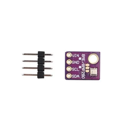
GY-BME280-3.3 Precision Altimeter Atmospheric Pressure Sensor Module
A 3.3V precision environmental sensor requiring a level shifter to interface with 5V Arduino — a perfect real-world use case for the techniques in this guide.
GY-BME280-5V Temperature and Humidity Sensor
The 5V-compatible version of the BME280 with onboard voltage regulation — plug directly into Arduino 5V without any level shifter needed.
Frequently Asked Questions
Can I connect a 3.3V sensor directly to an Arduino without a level shifter?
It depends on the direction. A 3.3V sensor’s output going to an Arduino input is generally safe — Arduino sees 3.3V as a valid HIGH. The dangerous direction is Arduino’s 5V output going to the 3.3V sensor’s input, which can exceed the sensor’s maximum input voltage. If you only need to read from the sensor (unidirectional), a resistor divider on the sensor’s output line may suffice. For any bidirectional communication (I2C, SPI), always use a proper level shifter.
Do I need a level shifter between a Raspberry Pi and an Arduino?
The Raspberry Pi’s GPIO runs at 3.3V and is NOT 5V-tolerant. Connecting Arduino’s 5V output directly to a Raspberry Pi GPIO input can permanently damage the Pi. Always use a level shifter or resistor divider. The Raspberry Pi to Arduino direction (3.3V → 5V Arduino input) is safe without a shifter since Arduino accepts 3.3V as HIGH.
What is the maximum speed of a BSS138 level shifter module?
Practically, BSS138 modules work reliably up to 400 kHz I2C (fast mode) and around 1–2 MHz for SPI. Above this, propagation delay and the RC time constant of the pull-up resistors + wire capacitance limit signal fidelity. For I2C at 400 kHz, reduce pull-up values to 2.2 kΩ on LV and 4.7 kΩ on HV side.
My I2C sensor works at 3.3V without a level shifter on Arduino. Should I still add one?
If it works, it may continue to work — Arduino’s 5V output may be within the sensor’s absolute maximum rating if the sensor includes internal ESD protection diodes. However, you’re operating outside specification, which risks long-term reliability degradation. For any permanent installation, add a level shifter for the SCL and SDA lines to guarantee the sensor operates within spec.
Is the BSS138 and 2N7002 interchangeable in level shifter circuits?
Yes, nearly identically. Both are N-channel enhancement-mode MOSFETs with similar threshold voltages (~1V), on-resistance, and package sizes (SOT-23). The 2N7002 has slightly higher breakdown voltage (60V vs 50V for BSS138) but this is irrelevant in a 5V logic application. Either part works in the level shifter circuit.
Do I need a level shifter for ESP8266 NodeMCU to sensor interfaces?
The ESP8266 NodeMCU runs entirely at 3.3V — its digital I/O is 3.3V logic and most pins have a 3.6V maximum input. When using it with 5V sensors or 5V TTL signals, you need a level shifter just as you would with an ESP32. The NodeMCU has slightly better ESD protection than bare ESP8266 modules, but still requires level shifting for reliable long-term operation with 5V signals.
Conclusion
The bidirectional logic level shifter is one of the most underappreciated components in any electronics maker’s toolkit. It bridges the gap between the legacy 5V world of Arduino and the modern 3.3V ecosystem that dominates contemporary sensor design, enabling you to safely connect thousands of modern sensor ICs, wireless modules, and co-processors that would otherwise be incompatible or at risk of damage.
Understanding why level shifting is needed — the physics of voltage thresholds and absolute maximum ratings — helps you make confident decisions about when a simple resistor divider suffices, when a BSS138 MOSFET circuit is the right tool, and when you need a dedicated IC like the PCA9306 or TXS0108 for demanding protocol speeds.
With a ₹30–80 generic 4-channel BSS138 level shifter module from an Indian electronics supplier, you can safely interface virtually any combination of 5V and 3.3V devices in your next Arduino, ESP32, or Raspberry Pi project — protecting your sensors, extending your hardware’s lifespan, and building with professional-grade reliability.
Find Sensors & Interface Modules at Zbotic
Browse our full range of environmental sensors, IMUs, and interface modules — all compatible with Arduino, ESP32, and Raspberry Pi. Fast shipping across India.


Add comment