
NRF24L01 Multiple Receivers: Hub and Spoke Network Arduino
The NRF24L01 transceiver module is a favourite among Indian Arduino makers for its low cost, 2.4GHz range, and ability to create multi-node wireless networks. In this tutorial, we’ll build a NRF24L01 hub and spoke network with multiple receivers on Arduino — a star topology where one central hub (master) communicates with up to 6 remote nodes (sensors) simultaneously. This is the foundation for DIY home sensor networks, wireless data loggers, and multi-room environmental monitoring systems.
NRF24L01 Overview: The 2.4GHz Transceiver
The NRF24L01 from Nordic Semiconductor is a 2.4GHz transceiver IC that operates in the globally unlicensed 2.4–2.525 GHz ISM band. At ₹30–₹80 per module, it’s one of the most affordable wireless solutions for short-to-medium range Arduino projects. Key features that make it perfect for multi-receiver networks:
- 6 data pipes: One NRF24L01 can simultaneously listen on up to 6 different “pipes” (addresses), enabling a hub to receive from 6 nodes without switching channels
- Auto-acknowledgement (ACK): Built-in hardware ACK with optional auto-retransmit — no need to implement reliability in software
- Enhanced ShockBurst: Hardware packet handling including CRC, retransmission, and acknowledgement
- Data rate: 250 kbps, 1 Mbps, or 2 Mbps selectable
- Range: 10–30 metres with PCB antenna; 50–100+ metres with NRF24L01+PA+LNA (external amplified variant)
- Power: 3.3V operation (5V tolerant on most Arduino outputs via RF24 library abstraction)
- Interface: SPI — SCK, MOSI, MISO, CS, CE
One critical point for Indian makers: the NRF24L01 requires a very stable 3.3V supply. The 3.3V pin on Arduino Uno can only supply ~150mA, which is often insufficient. Always add a 10µF capacitor (electrolytic) and a 0.1µF ceramic capacitor between VCC and GND of the NRF24L01, placed as close to the module as possible. Better yet, use a dedicated 3.3V LDO regulator like the AMS1117-3.3V.
Understanding Multi-Receiver Hub-Spoke Architecture
The hub-and-spoke (or star) topology is the most practical network design for home or lab sensor networks:
- Hub (Master/Central node): One Arduino that collects data from all sensor nodes. Connected to a display, SD card logger, WiFi module, or serial terminal. Opens all 6 listening pipes simultaneously.
- Spokes (Nodes/Sensor units): Up to 6 Arduino nodes, each with a sensor (temperature, humidity, gas, etc.). Each transmits to the hub using its unique pipe address.
How the NRF24L01 6-pipe system works: The NRF24L01 supports 6 receiving pipes (Pipe 0 through Pipe 5). Each pipe has a unique address (5 bytes). The hub opens all 6 pipes simultaneously. When any node transmits to the hub’s pipe address, the hub receives it and knows which pipe (and therefore which node) sent the data. Pipes 0 and 1 have full 5-byte unique addresses. Pipes 2–5 share the first 4 bytes of Pipe 1’s address and only differ in the last byte — this is an important hardware constraint.
Addressing scheme convention (RF24 library):
// Hub opens these 6 reading pipes:
// Pipe 0: 0x7878787878LL (used for ACKs, also listen)
// Pipe 1: 0xB3B4B5B6F1LL (Node 1)
// Pipe 2: 0xB3B4B5B6CD  (Node 2 — shares first 4 bytes of Pipe 1)
// Pipe 3: 0xB3B4B5B6A3  (Node 3)
// Pipe 4: 0xB3B4B5B60F  (Node 4)
// Pipe 5: 0xB3B4B5B605  (Node 5)
Wiring NRF24L01 to Arduino
NRF24L01 uses SPI. Here’s the standard wiring for Arduino Uno/Nano:
| NRF24L01 Pin | Arduino Uno/Nano Pin | Notes |
|---|---|---|
| GND | GND | Common ground |
| VCC | 3.3V | Add 10µF + 0.1µF capacitors! |
| CE | Digital Pin 7 | Chip Enable (any digital pin) |
| CSN | Digital Pin 8 | Chip Select (any digital pin) |
| SCK | Digital Pin 13 | SPI Clock (fixed) |
| MOSI | Digital Pin 11 | SPI Data Out (fixed) |
| MISO | Digital Pin 12 | SPI Data In (fixed) |
| IRQ | Optional (Pin 2 or 3) | Interrupt-driven RX (advanced) |
Install the RF24 library: Open Arduino IDE → Library Manager → search “RF24” → Install “RF24 by TMRh20” (the most maintained version). Also install “RF24Network” if you want mesh networking later.
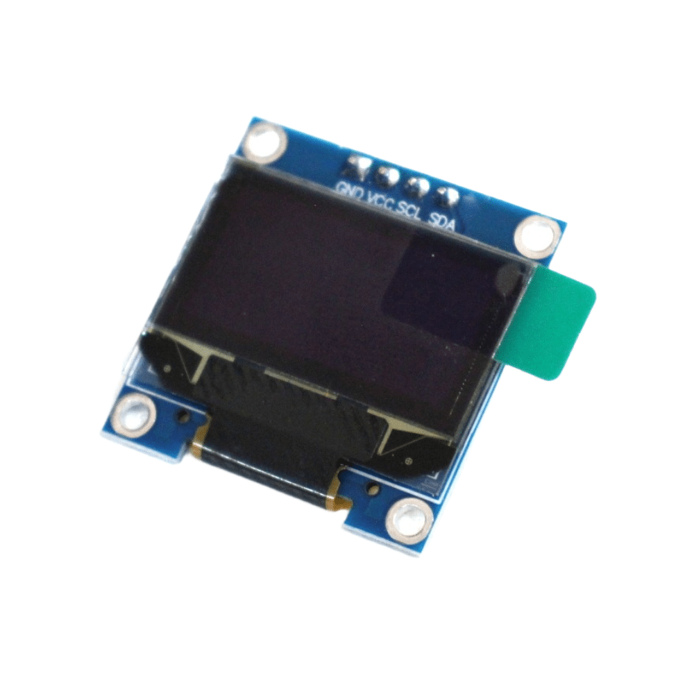
0.96 Inch I2C OLED LCD Module SSD1306 (White)
Add a local display to your NRF24L01 hub node to show real-time data from all sensor nodes. I2C interface leaves SPI pins free for the NRF24L01. Easy to use with Adafruit SSD1306 library.
Hub (Master) Code: Receiving from Multiple Nodes
The hub opens all 6 listening pipes and polls for incoming data, printing which node sent data and what it contained:
#include <SPI.h>
#include <RF24.h>

RF24 radio(7, 8); // CE, CSN pins

// 6 pipe addresses — nodes write TO these, hub listens on these
const uint64_t pipes[6] = {
  0x7878787878LL,   // Pipe 0 (also used for ACK)
  0xB3B4B5B6F1LL,  // Node 1
  0xB3B4B5B6CDLL,  // Node 2
  0xB3B4B5B6A3LL,  // Node 3
  0xB3B4B5B60FLL,  // Node 4
  0xB3B4B5B605LL   // Node 5
};

struct SensorData {
  uint8_t nodeId;
  float temperature;
  float humidity;
  uint32_t timestamp;
};

void setup() {
  Serial.begin(115200);
  radio.begin();
  radio.setPALevel(RF24_PA_LOW);  // Use RF24_PA_HIGH for longer range
  radio.setDataRate(RF24_250KBPS); // Slowest = best range and reliability
  radio.setChannel(108);           // Channel 108 = 2.508GHz, avoids WiFi
  radio.enableDynamicPayloads();
  radio.enableAckPayload();

  // Open all 6 reading pipes
  for (uint8_t i = 0; i < 6; i++) {
    radio.openReadingPipe(i, pipes[i]);
  }

  radio.startListening();
  Serial.println("Hub Ready — Listening on 6 pipes");
}

void loop() {
  uint8_t pipeNum;

  if (radio.available(&pipeNum)) {
    SensorData data;
    radio.read(&data, sizeof(data));

    Serial.print("Node "); Serial.print(pipeNum);
    Serial.print(" | Temp: "); Serial.print(data.temperature);
    Serial.print("°C | Humidity: "); Serial.print(data.humidity);
    Serial.println("%");
  }
}
Node (Spoke) Code: Each Sensor Transmitter
Each node is programmed identically except for one variable: which pipe address it writes to. Here’s the node code (change NODE_ID for each node from 1 to 5):
#include <SPI.h>
#include <RF24.h>

#define NODE_ID 1  // Change to 2, 3, 4, 5 for each node

RF24 radio(7, 8);

// Same pipe addresses as hub
const uint64_t pipes[6] = {
  0x7878787878LL,
  0xB3B4B5B6F1LL,
  0xB3B4B5B6CDLL,
  0xB3B4B5B6A3LL,
  0xB3B4B5B60FLL,
  0xB3B4B5B605LL
};

struct SensorData {
  uint8_t nodeId;
  float temperature;
  float humidity;
  uint32_t timestamp;
};

void setup() {
  Serial.begin(115200);
  radio.begin();
  radio.setPALevel(RF24_PA_LOW);
  radio.setDataRate(RF24_250KBPS);
  radio.setChannel(108);
  radio.enableDynamicPayloads();
  radio.enableAckPayload();

  // Node WRITES to its assigned pipe
  radio.openWritingPipe(pipes[NODE_ID]);
  // Node READS on Pipe 0 for ACKs
  radio.openReadingPipe(0, pipes[0]);

  radio.stopListening(); // Set to transmitter mode
  Serial.print("Node "); Serial.print(NODE_ID); Serial.println(" Ready");
}

void loop() {
  SensorData data;
  data.nodeId = NODE_ID;
  data.temperature = 28.5 + NODE_ID * 0.3; // Replace with real sensor read
  data.humidity = 65.0 + NODE_ID * 1.0;    // Replace with real sensor read
  data.timestamp = millis();

  bool success = radio.write(&data, sizeof(data));

  if (success) {
    Serial.println("Sent OK");
  } else {
    Serial.println("Send FAILED — ACK timeout");
  }

  delay(5000); // Send every 5 seconds
}
NRF24L01 Pipe Addresses Explained
Understanding NRF24L01 addressing prevents the most common beginner mistake in multi-node networks:
The 5-byte address rule: Each pipe has a 5-byte address. Pipe 0 and Pipe 1 can have completely independent 5-byte addresses. However, Pipes 2, 3, 4, and 5 must share the upper 4 bytes of Pipe 1’s address — only the lowest byte (LSB) can differ. This is a hardware constraint of the NRF24L01 chip.
Why this matters:
- Pipe 1 address:
0xB3 B4 B5 B6 F1 - Pipe 2 must be:
0xB3 B4 B5 B6 XX(any different XX) - Pipe 3 must be:
0xB3 B4 B5 B6 YY - …and so on for Pipes 4 and 5
Common addressing mistakes:
- Forgetting the LL suffix in Arduino code (uint64_t requires it)
- Mixing up which node writes to which pipe
- Not opening Pipe 0 on nodes for ACK reception
- Using the same address on multiple pipes
Channel selection: The 2.4GHz band is crowded in Indian homes (WiFi routers, Bluetooth, microwave ovens). Set the RF channel away from WiFi — Channels 100–125 (2.5–2.525 GHz) are above the standard WiFi range and significantly less congested. Use radio.setChannel(108) for a reliable choice.
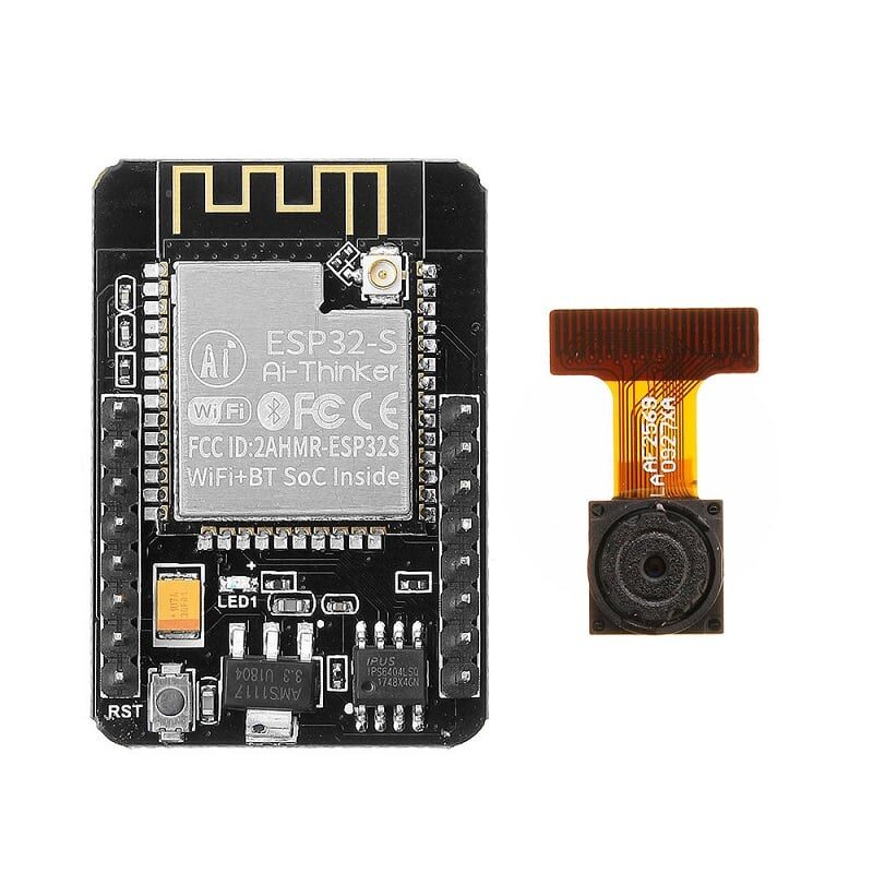
Ai Thinker ESP32 CAM Development Board WiFi+Bluetooth
Use this as your hub node to not only receive from NRF24L01 nodes via SPI but also forward data to a cloud server via WiFi — all on one board. The camera can also capture images triggered by sensor events.
Common Problems and Solutions
Problem: radio.begin() returns false or no communication
Solution: Almost always a power issue. Add 10µF + 0.1µF capacitors across VCC/GND of the NRF module. Try using a separate 3.3V supply. Check SPI wiring. Verify CE and CSN pin numbers match your code.
Problem: Hub receives data from Node 1 but not other nodes
Solution: Check pipe addressing — ensure Pipes 2–5 share the upper 4 bytes of Pipe 1’s address. Verify each node is writing to the correct unique pipe. Print the node ID in each packet to confirm which node is transmitting.
Problem: Frequent ACK timeouts in write()
Solution: Increase retransmit delay — radio.setRetries(15, 15) (15 = 4ms delay, 15 retries). Reduce data rate to 250kbps for better range. Check for RF interference by trying different channels. Ensure both hub and nodes use the same data rate and channel.
Problem: Works on desk but fails after assembly in enclosure
Solution: Metal enclosures block RF signals. Use plastic or ABS enclosures. If metal is required, route the antenna outside the box. Also ensure the NRF24L01 antenna doesn’t touch metal traces on your PCB.
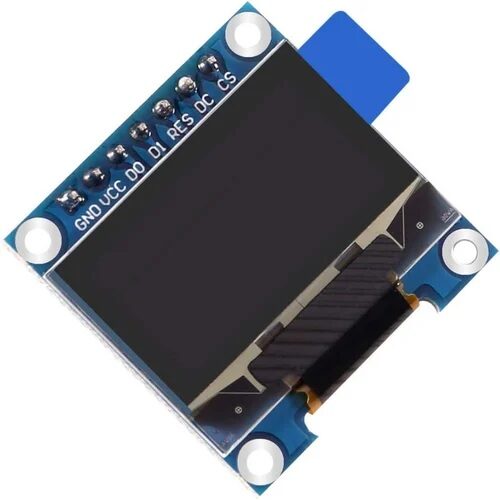
0.96 Inch SPI OLED LCD Module 7pin SSD1306
SPI-based OLED for advanced hub displays. Faster refresh than I2C, ideal for showing live data from all 6 nodes simultaneously with scrolling or tabbed display layouts.
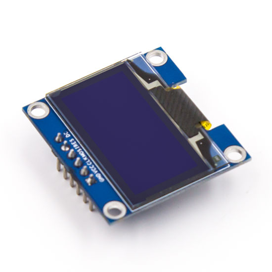
0.96 Inch SPI OLED LCD Module 6pin Blue SSD1306
Blue OLED variant for distinctive status displays. Use on individual sensor nodes to show local readings and NRF24L01 transmission status. Low power consumption, visible in all lighting conditions.
Frequently Asked Questions
How many NRF24L01 nodes can one hub handle?
The NRF24L01 hardware supports 6 receiving pipes, so a single hub can directly communicate with 6 nodes simultaneously. For larger networks (7+ nodes), use the RF24Network or RF24Mesh library, which implements a tree topology where intermediate nodes relay messages. RF24Mesh can theoretically handle hundreds of nodes in a mesh arrangement.
Can NRF24L01 nodes talk to each other directly (not just to the hub)?
Each NRF24L01 is a full transceiver — it can both transmit and receive. In the basic hub-spoke setup described here, nodes only talk to the hub. For node-to-node communication, use the RF24Network library which routes messages through the hub or intermediate nodes. Direct node-to-node requires stopping listening on one pipe, switching to write mode, sending, then switching back.
What’s the difference between NRF24L01 and NRF24L01+PA+LNA?
The standard NRF24L01 (PCB antenna) has a built-in 0dBm transmit power and about -82dBm sensitivity — range ~10–30 metres indoors. The NRF24L01+PA+LNA variant adds a Power Amplifier (+20dBm TX) and Low Noise Amplifier (better RX sensitivity), extending range to 100–1000 metres in open areas. The PA+LNA version needs more current (up to 115mA TX) and requires a cleaner power supply, but is worth it for whole-house coverage.
Can I use NRF24L01 with ESP32 or ESP8266 instead of Arduino?
Yes, the RF24 library supports ESP8266 and ESP32. For ESP32, use SPI pins: SCK=18, MISO=19, MOSI=23, SS=5 (hardware SPI). CE and CSN can be any digital pins. The ESP32 hub is particularly powerful because it can receive from all NRF24L01 nodes and simultaneously forward data to a cloud server (MQTT, ThingSpeak, Google Sheets) via WiFi — no extra hardware needed.
Why does my NRF24L01 work intermittently?
Intermittent operation is almost always a power supply problem. Add a 10µF electrolytic capacitor and a 0.1µF ceramic capacitor between VCC and GND of the NRF24L01 module, placed as close to the module pins as possible. The capacitors handle current transients during transmission bursts. If you’re powering from Arduino’s 3.3V pin, consider switching to a dedicated AMS1117-3.3V LDO regulator powered from 5V — the Arduino’s 3.3V regulator is often current-limited.
Build Your NRF24L01 Sensor Network with Zbotic
Get OLED displays, ESP32 boards, and all the accessories you need to build a complete multi-node wireless sensor network — sourced from Zbotic, India’s trusted electronics store for makers.


Add comment