
If you have ever built a basic line follower robot and wondered why it wobbles, overshoots, or loses the line at speed, the answer is almost certainly that the PID line follower robot tuning speed competition problem you’re facing comes down to controller gains. PID — Proportional, Integral, Derivative — is the mathematical heart of every fast, smooth line-following robot. This guide teaches you not just what PID does, but how to tune it systematically so your robot can compete and win.
Understanding PID Control
PID stands for three independently tunable terms that work together to minimise the error between where your robot is and where it should be on the line.
- P (Proportional): Applies a correction proportional to the current error. High Kp = aggressive steering; too high = oscillation.
- I (Integral): Accumulates past errors over time to eliminate steady-state offset. High Ki = eliminates drift; too high = slow wobble that grows.
- D (Derivative): Predicts future error based on the rate of change. High Kd = dampens oscillation; too high = jittery motors reacting to noise.
The PID output drives differential speed: left motor gets base_speed − PID_output and right motor gets base_speed + PID_output (or vice versa depending on your convention). A positive error (robot drifted right) gives a positive output, steering left to correct.
For a competition robot, the goal is to find the highest base speed at which the PID can still track the sharpest turn on the course without overshooting and losing the line.
Hardware Setup for Competition
Competition line-follower robots in India typically follow the Techfest, Robocon, or e-Yantra rules using a 3 cm white line on black background (or vice versa). Typical hardware:
- Microcontroller: Arduino Nano (compact, 16 MHz, sufficient PWM outputs)
- Motors: N20 micro metal geared motors at 500–1000 RPM for speed; or JGA25 planetary motors for torque
- Motor driver: TB6612FNG (lower voltage drop than L298N, crucial at competition speed)
- Sensor array: 5 or 8 IR sensor modules (TCRT5000-based), spaced 12–15 mm apart
- Power: 2S LiPo (7.4V) for motors, 5V regulator for logic — never mix on the same rail
- Chassis: Minimise weight. Use PCB-integrated chassis if possible.
Frame rigidity matters. A flexing chassis changes sensor-ground clearance mid-run, throwing off your calibrated readings. Use 3 mm acrylic or thin aluminium with the sensor bar mounted rigidly at 2–5 mm above the surface.
IR Sensor Array and Position Calculation
The key innovation in competition-grade line followers is replacing binary per-sensor logic with a weighted average position. Instead of just knowing “line is under sensor 3”, you know “line is at position +120 from centre” — a continuous error signal ideal for PID.
// 5-sensor position calculation
// Sensors: S0(leftmost) to S4(rightmost)
// Weights: -2, -1, 0, +1, +2

int sensorWeights[5] = {-200, -100, 0, 100, 200};

int readPosition() {
  int weighted_sum = 0;
  int total_active = 0;
  for (int i = 0; i < 5; i++) {
    int val = digitalRead(sensorPin[i]) == LOW ? 1 : 0; // LOW = line detected
    weighted_sum += val * sensorWeights[i];
    total_active += val;
  }
  if (total_active == 0) return lastPosition; // all off-line: use last known
  lastPosition = weighted_sum / total_active;
  return lastPosition;
}
Calibration: Before each run, slowly drag the robot across the line 10–15 times. Store min/max analog readings per sensor and normalise them to 0–1000. This compensates for LED aging, surface colour variation, and ambient light — critical in indoor competition halls with mixed lighting.
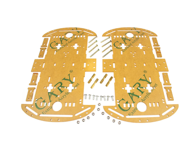
4 Wheels Car Chassis Acrylic Frame
Lightweight acrylic 4WD chassis — ideal base for building a competition line follower robot with room for sensor bar and battery.
Arduino PID Code
Here is a complete, competition-ready PID line-follower sketch. Tune Kp, Ki, Kd per the method described in the next section.
// PID Line Follower — Zbotic.in
// TB6612FNG motor driver, 5 IR sensors

#define PWMA 9   // Left motor speed
#define AIN1 2   // Left motor dir
#define AIN2 3
#define PWMB 10  // Right motor speed
#define BIN1 4   // Right motor dir
#define BIN2 5
#define STBY 6   // Standby pin (set HIGH)

const int sensorPin[5] = {A0, A1, A2, A3, A4};
const int sensorWeights[5] = {-200, -100, 0, 100, 200};

float Kp = 0.8, Ki = 0.001, Kd = 5.0;
int BASE_SPEED = 160;
int MAX_SPEED = 255;

float error = 0, prev_error = 0, integral = 0;
int lastPosition = 0;

void setup() {
  for (int i = 0; i < 5; i++) pinMode(sensorPin[i], INPUT);
  pinMode(PWMA, OUTPUT); pinMode(AIN1, OUTPUT); pinMode(AIN2, OUTPUT);
  pinMode(PWMB, OUTPUT); pinMode(BIN1, OUTPUT); pinMode(BIN2, OUTPUT);
  pinMode(STBY, OUTPUT); digitalWrite(STBY, HIGH);
}

void setMotors(int left, int right) {
  left  = constrain(left,  -MAX_SPEED, MAX_SPEED);
  right = constrain(right, -MAX_SPEED, MAX_SPEED);
  // Left
  analogWrite(PWMA, abs(left));
  digitalWrite(AIN1, left >= 0 ? HIGH : LOW);
  digitalWrite(AIN2, left >= 0 ? LOW  : HIGH);
  // Right
  analogWrite(PWMB, abs(right));
  digitalWrite(BIN1, right >= 0 ? HIGH : LOW);
  digitalWrite(BIN2, right >= 0 ? LOW  : HIGH);
}

int readPosition() {
  int ws = 0, tot = 0;
  for (int i = 0; i < 5; i++) {
    int v = analogRead(sensorPin[i]) > 600 ? 1 : 0; // adjust threshold
    ws += v * sensorWeights[i];
    tot += v;
  }
  if (tot == 0) return lastPosition;
  return lastPosition = ws / tot;
}

void loop() {
  error = readPosition();
  integral += error;
  integral = constrain(integral, -3000, 3000); // anti-windup
  float derivative = error - prev_error;
  float output = Kp * error + Ki * integral + Kd * derivative;
  prev_error = error;

  int leftSpeed  = BASE_SPEED - (int)output;
  int rightSpeed = BASE_SPEED + (int)output;
  setMotors(leftSpeed, rightSpeed);
}
Step-by-Step Tuning Method
Proper PID tuning is an iterative process. Follow this sequence precisely:
- Start with all gains at zero. Set Kp = 0.1, Ki = 0, Kd = 0. Place robot on a straight line at low speed (BASE_SPEED = 100). It should follow but drift lazily.
- Increase Kp by 0.1 each run until the robot starts to oscillate (left-right wobble on a straight section). Back off to 70% of that value. This is your working Kp.
- Add Kd. Start at Kd = Kp × 5. Increase until oscillation damps — the robot should now take curves more smoothly. Typical Kd = 3–10× Kp.
- Add Ki last. Use Ki = 0.001. This corrects very slow drift. If you see integral wind-up (sluggish recovery after an overshoot), add the anti-windup clamp shown in the code above.
- Increase BASE_SPEED by 10 per run. Recalibrate Kd upward as speed increases — at high speed, the derivative term needs to be larger to prevent overshoot on sharp bends.
Keep a tuning log. Write down each Kp/Ki/Kd set and the corresponding speed, and note where the robot loses the line. The optimal set is usually 5–10 runs before the failure point.
Competition Speed Tips
Beyond PID, there are mechanical and strategic tips that separate podium finishers from first-round eliminations at Indian robotics competitions:
- Sensor height matters more than sensor count. 2–4 mm above the surface gives the best contrast reading. Use a stiff adjustable mount and check it before every run.
- Use a LiPo, not AA batteries. Alkaline batteries sag under load. A 2S LiPo delivers consistent voltage and the robot behaves identically in practice and competition.
- Pre-run calibration is non-negotiable. Ambient lighting in competition halls varies. Always re-calibrate on the actual competition surface 10 minutes before your run.
- Shorten update loop. Remove all
Serial.print()anddelay()from your loop. The PID should sample at 1–5 ms intervals for smooth high-speed control. - Memorise the track layout if rules allow. Use a lookup table of “sharp left incoming” to temporarily reduce base speed and prevent line loss on tight turns.
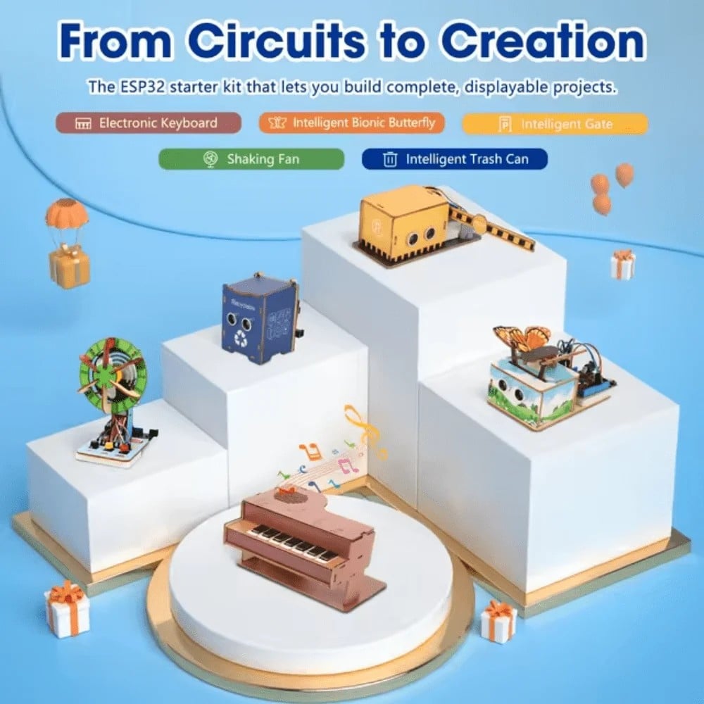
ACEBOTT ESP32 Basic Starter Kit – QE201
Comprehensive ESP32 project expansion kit — great for upgrading your line follower with WiFi telemetry and real-time PID monitoring.
Advanced Tricks for Intersections
Most competition tracks include T-junctions, crossroads, and dead-ends. Basic PID handles straight runs and curves but fails at intersections where all sensors suddenly see the line. Here is how to handle them:
Junction Detection
If three or more sensors see the line simultaneously, you are at an intersection. Pause the PID output, execute a timed turn (pre-measured for your motor speed), then resume PID. Store turn decisions in a const char* path = "LRLS"; string consumed character by character.
Line-Loss Recovery
When total_active == 0 (all sensors off the line), execute a spin in the direction of the last known error until any sensor sees the line. Set a timeout of 800 ms — if still not found, stop and flag a recovery fail.
Speed Zones
Detect the error magnitude. If abs(error) > 150, reduce BASE_SPEED by 30% before applying PID. This allows the robot to fly on straights but slow intelligently into curves — mimicking what a human driver would do.
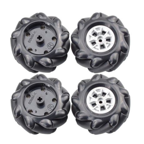
60MM-K Mecanum Wheel (Pack of 4) – Black
Upgrade your robot with omnidirectional Mecanum wheels — perfect for intersection navigation and advanced competition manoeuvres.
Frequently Asked Questions
What is a good PID starting point for a TCRT5000 sensor 4WD robot?
Start with Kp = 0.5, Ki = 0, Kd = 3.0 at BASE_SPEED = 120. This is conservative enough to stay on the line while you calibrate sensors. Increase Kp and speed once the robot tracks a gentle curve reliably.
How many IR sensors do I need for a competition line follower?
5 sensors is the sweet spot for most Indian competitions. 3 sensors are too coarse for sharp turns; 8 sensors add weight and complexity without proportional benefit unless the track has extremely tight sub-centimetre curves.
Why does my robot oscillate even with low Kp?
Check sensor polling speed. If your loop takes more than 10 ms per cycle, the derivative term is working on stale data and actually causes oscillation. Remove all blocking calls from the loop and measure loop time with micros().
Can I use PID on an ESP32 line follower?
Yes, and ESP32 is actually better — faster CPU means tighter loop timing, and you can transmit PID state over WiFi to a phone for real-time monitoring, making tuning much faster.
What is the maximum speed achievable in Indian line follower competitions?
Competitive robots using N20 500 RPM motors and well-tuned PID can reach 0.8–1.2 m/s on standard tracks. Some advanced designs using brushless motors and encoder feedback exceed 2 m/s on straight sections.
Get competition-ready components fast! Shop line follower sensor arrays, motor drivers, robot chassis, and LiPo batteries at Zbotic.in – Robotics & DIY. All orders ship from India with same-day dispatch on most items.


Add comment