
Battery Capacity Tester Circuit with Arduino & LCD Display
A battery capacity tester Arduino LCD project is one of the most practical builds any electronics hobbyist can make. Whether you are trying to verify the true capacity of a new 18650 cell (to confirm it is not a fake), reviving old laptop battery cells for a power wall project, or sorting used cells by actual energy storage before building a pack — a homemade capacity tester gives you real data you cannot get any other way. This guide walks through the complete design, code, and assembly of an Arduino-based battery capacity tester that displays live readings on an LCD and logs the final mAh on screen.
How Battery Capacity Testing Works
Battery capacity (measured in mAh or Ah) is defined as the total charge a battery can deliver from full charge to the cutoff voltage at a specified discharge rate. The principle is simple:
Capacity (mAh) = Average Current (mA) × Discharge Time (hours)
In practice, since current and voltage vary over the discharge curve, we integrate current over time using small time intervals:
mAh = Σ (I_instantaneous × Δt)
where Δt = measurement interval (e.g., every 1 second = 1/3600 hours)
Our Arduino reads the cell voltage and load current (via a shunt resistor) every second, adds that instant’s charge contribution to a running total, and stops when the cell voltage drops to the cutoff threshold (3.0 V for Li-Ion). The total accumulated charge is the true capacity of that cell.
This method is called Coulomb counting and is the same principle used in professional battery analysers — it is just implemented here with a ₹200 Arduino Nano instead of a ₹5000 instrument.
Components Required
| Component | Specification | Notes |
|---|---|---|
| Arduino Nano | ATmega328P, 5V | Any Arduino works; Nano is compact |
| 16×2 LCD with I2C module | HD44780 + PCF8574 I2C backpack | Reduces wiring to 4 wires (VCC, GND, SDA, SCL) |
| Power resistor (load) | 5Ω / 10W wirewound | Sets ~800 mA discharge current for a 4V cell |
| Shunt resistor | 0.1Ω / 1% / 1W | For current measurement via voltage drop |
| N-channel MOSFET | IRLZ44N or IRF540N | Controls load on/off via Arduino digital pin |
| Voltage divider resistors | 10 kΩ + 10 kΩ (1%) | Scale 4.2V battery to 2.1V for Arduino ADC (0–5V range) |
| 18650 cell holder | Single cell, 18.4 mm bore | Connect cell under test here |
| 100 µF electrolytic cap | 10 V rated | Across battery terminals for noise filtering |
| Heatsink | TO-220 clip-on | Required on power resistor and MOSFET |
| Tactile pushbutton | SPST, through-hole | Start/reset button |
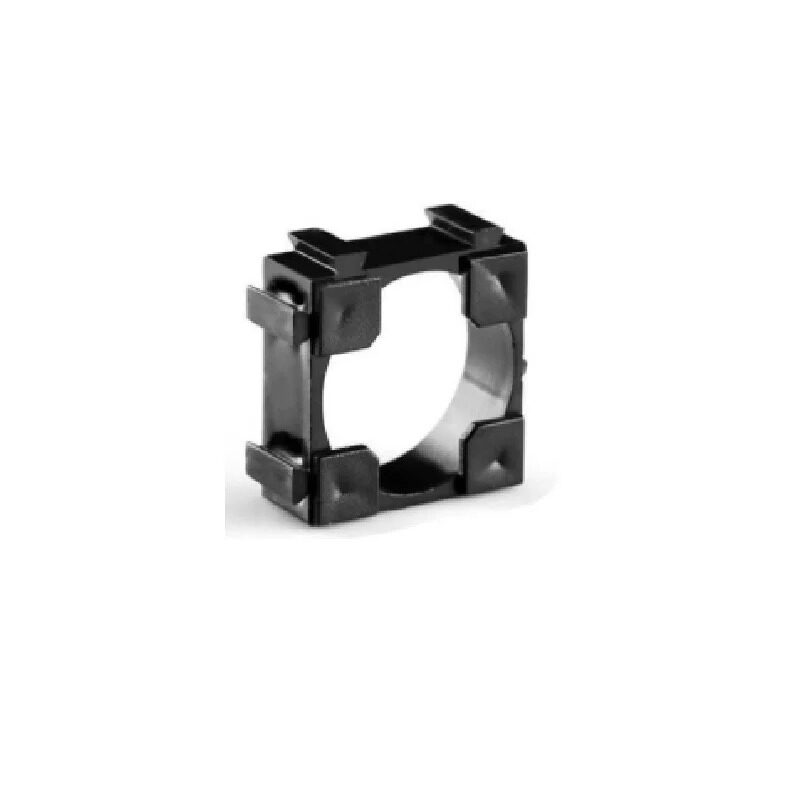
1 x 18650 Battery Holder with 18.4MM Bore Diameter – Pack of 4
The test socket for your capacity tester. The 18.4 mm bore fits genuine 18650 cells perfectly. Spring contacts minimise contact resistance, which is critical for accurate current measurement through the shunt resistor.
Circuit Diagram & Connections
Here is the complete wiring in text form:
BATTERY (+) ──────┬──────── Voltage Divider ──── Arduino A0
                  │         (10k + 10k to GND)
                  │
                  └──────── Shunt (0.1Ω) ──┬──── Drain of MOSFET
                                           │
                                           └──── Arduino A1 (shunt voltage)

MOSFET Source ─── Load Resistor (5Ω/10W) ─── BATTERY (-) / GND
MOSFET Gate   ─── Arduino D9 (PWM, optional; use D8 for simple on/off)
MOSFET Gate   ─── 10kΩ pull-down to GND

Arduino 5V ─── LCD VCC (via I2C backpack)
Arduino GND ── LCD GND
Arduino A4 (SDA) ── LCD SDA
Arduino A5 (SCL) ── LCD SCL

Start Button: D2 to VCC, 10kΩ pull-down to GND
Arduino powered from USB (separate 5V source, NOT the battery under test)
Key design point: The Arduino must be powered from a separate 5V USB source, not the battery under test. If you power Arduino from the test battery, the measurement reference changes as the battery voltage changes — causing ADC errors. Use your computer’s USB port or a phone charger to power the Arduino during testing.
Arduino Code Walkthrough
Below is the complete Arduino sketch. Copy this into the Arduino IDE and upload to your Nano.
#include <Wire.h>
#include <LiquidCrystal_I2C.h>

// --- Configuration ---
const int LOAD_PIN = 8;        // MOSFET gate control
const int BTN_PIN = 2;         // Start/reset button
const int VOLT_PIN = A0;        // Battery voltage divider
const int CURR_PIN = A1;        // Shunt voltage (current sense)

const float SHUNT_R = 0.1;      // Shunt resistor in Ohms
const float V_REF = 5.0;        // Arduino ADC reference (5V)
const float V_CUTOFF = 3.0;     // UVP cutoff voltage for Li-Ion
const float DIVIDER_RATIO = 2.0; // 10k+10k divider (x2 to get real voltage)

LiquidCrystal_I2C lcd(0x27, 16, 2);

float totalMAh = 0.0;
bool testing = false;
bool done = false;

void setup() {
  pinMode(LOAD_PIN, OUTPUT);
  digitalWrite(LOAD_PIN, LOW);
  pinMode(BTN_PIN, INPUT);
  lcd.init();
  lcd.backlight();
  lcd.print("Battery Tester");
  lcd.setCursor(0,1);
  lcd.print("Press BTN Start");
}

void loop() {
  if (digitalRead(BTN_PIN) == HIGH && !testing && !done) {
    delay(50); // debounce
    totalMAh = 0.0;
    testing = true;
    digitalWrite(LOAD_PIN, HIGH);
    lcd.clear();
    lcd.print("Testing...");
  }

  if (digitalRead(BTN_PIN) == HIGH && done) {
    done = false;
    lcd.clear();
    lcd.print("Battery Tester");
    lcd.setCursor(0,1);
    lcd.print("Press BTN Start");
  }

  if (testing) {
    // Read battery voltage (average 10 samples)
    float vRaw = 0;
    for(int i=0; i<10; i++) vRaw += analogRead(VOLT_PIN);
    vRaw /= 10.0;
    float vBat = (vRaw / 1023.0) * V_REF * DIVIDER_RATIO;

    // Read shunt voltage → current
    float sRaw = 0;
    for(int i=0; i<10; i++) sRaw += analogRead(CURR_PIN);
    sRaw /= 10.0;
    float vShunt = (sRaw / 1023.0) * V_REF;
    float current_mA = (vShunt / SHUNT_R) * 1000.0;

    // Accumulate charge (1 second interval → /3600 to convert to mAh)
    totalMAh += current_mA / 3600.0;

    // Display live readings
    lcd.setCursor(0,0);
    lcd.print("V:"); lcd.print(vBat, 2);
    lcd.print("  I:"); lcd.print((int)current_mA);
    lcd.print("mA ");
    lcd.setCursor(0,1);
    lcd.print("Cap:"); lcd.print((int)totalMAh);
    lcd.print(" mAh    ");

    // Check cutoff
    if (vBat <= V_CUTOFF) {
      digitalWrite(LOAD_PIN, LOW);
      testing = false;
      done = true;
      lcd.clear();
      lcd.print("DONE! Cap:");
      lcd.setCursor(0,1);
      lcd.print((int)totalMAh);
      lcd.print(" mAh");
    }

    delay(1000); // 1 second sample interval
  }
}
Setting Up the LCD Display
The project uses a 16×2 LCD with an I2C backpack module (PCF8574 chip). This reduces the wiring from 12 pins to just 4 (VCC, GND, SDA, SCL). Install the required library before uploading the code:
- Open Arduino IDE → Sketch → Include Library → Manage Libraries
- Search for “LiquidCrystal I2C” by Frank de Brabander
- Install the latest version
If your LCD shows nothing or just block squares, adjust the I2C address. The default is 0x27 but some modules use 0x3F. Use an I2C scanner sketch to detect the correct address. Also turn the contrast potentiometer on the backpack module clockwise until characters appear.
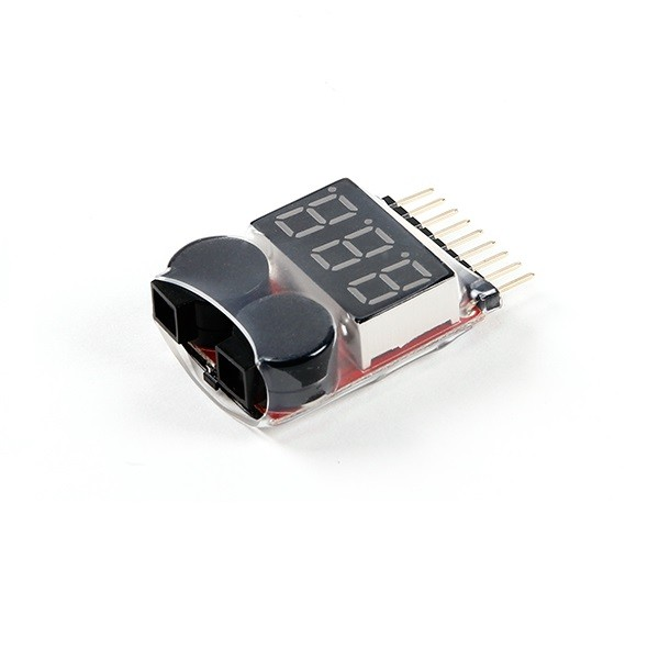
1-8S Lipo Battery Voltage Tester Without Alarm
Use this alongside your Arduino tester for quick cell-level voltage verification before and after a capacity test. Confirms the cell reached full charge before the discharge test begins, ensuring accurate results.
Calibration & Accuracy Tips
The Arduino ADC is 10-bit (1024 steps), and its reference voltage may not be exactly 5.0 V. Here is how to improve accuracy:
Calibrate the Voltage Divider
Measure the actual voltage divider output with a calibrated multimeter, then compare with the Arduino’s A0 reading. Calculate the actual ratio and update the DIVIDER_RATIO constant in the code. Example: if the meter reads 2.08 V at A0 when the battery is 4.16 V, the ratio is 4.16/2.08 = 2.0 — correct. If the ratio is different, update accordingly.
Calibrate the Arduino Reference
Measure your Arduino’s actual 5V pin with a calibrated meter. If it reads 4.97 V, update V_REF = 4.97 in the code. This alone can correct a 0.6% systematic error across all voltage and current readings.
Use Precision Resistors
The voltage divider resistors and shunt resistor should be 1% tolerance (metal film). Standard 5% carbon film resistors introduce errors of up to ±5% in each reading, compounding to ±10% in the final mAh result. Use matched-pair resistors from the same batch for the voltage divider.
Heatsink the Load Resistor
A 5Ω resistor at 800 mA dissipates 3.2 W. Without a heatsink, the resistor temperature rises and its resistance drifts (positive temperature coefficient for most wirewound resistors). This causes the discharge current to decrease as resistance increases, making the cell appear to have less capacity. Use a heatsink and keep the resistor cool for consistent readings.
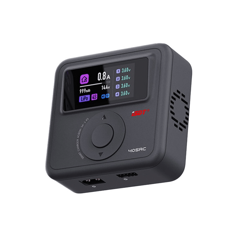
ISDT 405AC 60W GaN Smart Charger
Before running a capacity test, fully charge your 18650 cell to 4.2V with a precise CC/CV charger. The ISDT 405AC ensures accurate top-charge every time — the starting point that determines the accuracy of your capacity measurement.
Reading & Interpreting Your Results
Once the test completes, the LCD shows the final capacity. Here is how to interpret the numbers:
| Measured Capacity | Cell Condition | Action |
|---|---|---|
| >90% of rated capacity | Excellent — near-new condition | Use in high-performance builds |
| 70–90% of rated capacity | Good — some age-related fade | Use in lower-drain applications |
| 50–70% of rated capacity | Degraded — significant capacity loss | Sort into lower-capacity packs |
| <50% of rated capacity | Failed — excessive degradation | Recycle responsibly |
| <20% of rated capacity | Fake or deeply failed cell | Do not use; dispose safely |
For a cell labelled “2500 mAh” (Samsung 25R): a genuine cell should measure 2300–2600 mAh at the 800 mA discharge rate used by this tester. If it measures 900 mAh or less, it is either a badly degraded genuine cell or a counterfeit.
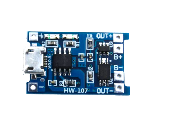
TP4056 1A Li-Ion Battery Charging Board with Protection
After each capacity test, safely recharge your cell with this TP4056 module. Perfect CC/CV charging at 1A with automatic cutoff at 4.2V — ensures cells are correctly topped up for repeated test cycles.
Frequently Asked Questions
Why does my tester show a different result from the cell’s rated capacity?
Cell capacity is rated at a standard discharge rate (usually C/5 or C/10 — very slow). Your tester discharges at approximately 0.3C for a 2500 mAh cell, which is slightly faster. Higher discharge rates give slightly lower capacity readings due to internal resistance losses. A 2500 mAh cell might read 2200–2400 mAh at your tester’s discharge rate — this is normal. If it reads below 2000 mAh, the cell has genuinely degraded.
Can I test NiMH or lead-acid batteries with this tester?
Yes, with modifications. Change the V_CUTOFF constant: for NiMH use 1.0 V per cell, for 6V lead-acid use 5.25 V total. Also adjust the voltage divider ratio for different voltage ranges. For NiMH (1.2 V nominal), the voltage divider is not needed — you can read directly on the Arduino ADC since the voltage is already within 0–5V range. For lead-acid packs above 5V, ensure your voltage divider scales correctly.
How do I add data logging to save results to an SD card?
Add an SD card module (SPI interface) to the project. Include the Arduino SD library and use File dataFile = SD.open("log.csv", FILE_WRITE) to log voltage, current, mAh, and timestamp every second. This creates a CSV file you can import into Excel or Google Sheets to plot the full discharge curve — far more informative than just the final mAh number.
Is it safe to leave the tester running unattended?
The tester automatically cuts off the load when the cell reaches 3.0 V, so it will not over-discharge the cell. However, the power resistor gets hot (up to 60–80°C), so always place the tester on a fireproof surface (ceramic tile, metal sheet). Do not leave it unattended in the first few tests until you have confirmed the heatsink is adequate and the resistor temperature stabilises safely.
How many test cycles does it take to get a reliable capacity reading?
For a brand new cell, run two full charge-discharge-charge cycles before the capacity test. New cells often need a formation cycle or two to reach their rated capacity. For used cells, one cycle is sufficient — the capacity you measure is representative of the cell’s current state. For the most accurate result, use the average of three consecutive test cycles.
Get Your Battery Testing Components from Zbotic
Find genuine 18650 holders, BMS boards, TP4056 charging modules, and ISDT smart chargers at Zbotic.in — fast shipping across India for all your battery project needs.


Add comment