
Buck-Boost Converter: When and How to Use Them
If you’ve ever needed to power a 5V circuit from a battery that might be anywhere from 3.2V to 6V, you’ve already stumbled into the exact problem a buck-boost converter solves. Unlike a simple buck (step-down) or boost (step-up) converter, a buck-boost converter handles both cases — it can step voltage up or down depending on what the load demands. For Indian hobbyists, makers, and engineers building battery-powered devices, robotics, or portable gadgets, understanding the buck-boost converter is essential power electronics knowledge.
What Is a Buck-Boost Converter?
A buck-boost converter is a type of DC-DC switching power supply that can produce an output voltage that is either higher or lower than its input voltage. It gets its name from its two operating modes:
- Buck mode: When input voltage is higher than the desired output (like stepping 12V down to 5V)
- Boost mode: When input voltage is lower than the desired output (like stepping 3.7V up to 5V)
The magic happens seamlessly — a well-designed buck-boost controller transitions between modes automatically based on input-output voltage differential. This makes it indispensable in battery-powered applications where the battery voltage sags as it discharges, passing through and below the target output voltage.
Common examples include:
- Single-cell Li-ion (3.0–4.2V) powering a 3.3V microcontroller — the battery starts above 3.3V and ends below it
- Solar panel systems with variable harvested voltage feeding a fixed-voltage load
- LED drivers requiring constant current regardless of input fluctuation
- Automotive systems where 12V battery can swing from 9V to 15V during cranking and alternator operation
How Does It Work? The Working Principle
At its core, a non-inverting buck-boost converter (also called a 4-switch buck-boost) uses four MOSFETs and an inductor to transfer energy. Let’s trace through the operation:
Energy Storage Phase (Switch ON)
When the main switching element (typically a MOSFET) turns on, current flows through the inductor, storing energy in its magnetic field. The inductor current ramps up linearly according to V = L × (di/dt).
Energy Release Phase (Switch OFF)
When the switch turns off, the inductor’s magnetic field collapses, releasing its stored energy to the output through a freewheeling diode (or synchronous MOSFET). In buck mode, only the input-to-inductor switches operate. In boost mode, only the inductor-to-output switches operate. The controller blends both phases for voltages near the crossover point.
PWM Control
A PWM (Pulse Width Modulation) controller adjusts the duty cycle to maintain constant output voltage. The duty cycle D = Vout / (Vin + Vout) for an inverting buck-boost, or more complex for non-inverting topologies. Feedback from the output voltage closes the control loop.
Key Electrical Parameters
- Efficiency: Typically 85–95% for modern ICs
- Switching frequency: 100 kHz to 2 MHz (higher = smaller inductors but more switching losses)
- Ripple voltage: Output ripple depends on output capacitance and inductor value
- Inductor current: Peak inductor current = Iout × (1 + ripple factor/2)
Types of Buck-Boost Topologies
Not all buck-boost converters are architecturally identical. Here are the main topologies you’ll encounter:
1. Inverting Buck-Boost
The simplest topology — uses a single switch and produces an output voltage of opposite polarity to the input. If you feed it +12V, you get -5V out (for example). Useful in op-amp circuits needing split supplies, but awkward when you need positive output from positive input.
2. SEPIC (Single-Ended Primary Inductance Converter)
Produces a positive output from a positive input, using two coupled inductors and a series capacitor. Non-inverting, but more complex and slightly less efficient. Popular in battery chargers and LED drivers.
3. Ćuk Converter
Similar to SEPIC but produces inverted output. Known for very low input and output current ripple. Uses a capacitor for energy transfer between stages.
4. 4-Switch Non-Inverting Buck-Boost
The most sophisticated topology — uses four MOSFETs controlled by a smart IC. Delivers high efficiency across the entire operating range and is the topology used in premium IC solutions like TI’s TPS63xxx series or the LTC3780. This is what you’ll find in high-end ready-made modules.
5. H-Bridge Buck-Boost
Common in bidirectional power flow applications like battery management systems and motor drives. Can charge and discharge a battery from the same converter.
When Should You Use a Buck-Boost Converter?
The key question to ask is: does my input voltage range overlap with my output voltage requirement? If yes, you need a buck-boost. Here are concrete scenarios:
Scenario 1: Single Li-Ion Cell to 5V USB Power
A fully charged 18650 cell is 4.2V; a depleted cell is 3.0V. A USB device needs 5V. Neither a pure buck (always needs input > output) nor a pure boost (output always higher than input) works alone. A buck-boost converter handles the full 3.0–4.2V input range while maintaining a steady 5V output.
Scenario 2: 2S LiPo Battery (6.0–8.4V) Powering a 7.4V System
The nominal voltage sits right at the target. When fully charged (8.4V), you need to buck it down. When partially drained (below 7.4V), you need to boost it. A buck-boost converter is the only clean solution.
Scenario 3: Solar Energy Harvesting
Solar panel voltage fluctuates with sunlight intensity. A MPPT (Maximum Power Point Tracking) controller using a buck-boost topology can extract maximum power regardless of the panel voltage versus battery voltage relationship.
Scenario 4: Automotive Electronics (8V–16V Input, 12V Output)
A car’s electrical system is nominally 12V but can drop to 8V during cold crank start and spike to 14.4V when the alternator is running hard. A 12V buck-boost converter ensures your sensitive electronics always see exactly 12V.
When NOT to Use a Buck-Boost Converter
If your input voltage is always higher than your output voltage, a simpler and more efficient buck converter is sufficient. If your input is always lower, use a boost converter. Buck-boost converters have slightly higher component count and cost — don’t use them where a simpler solution works.
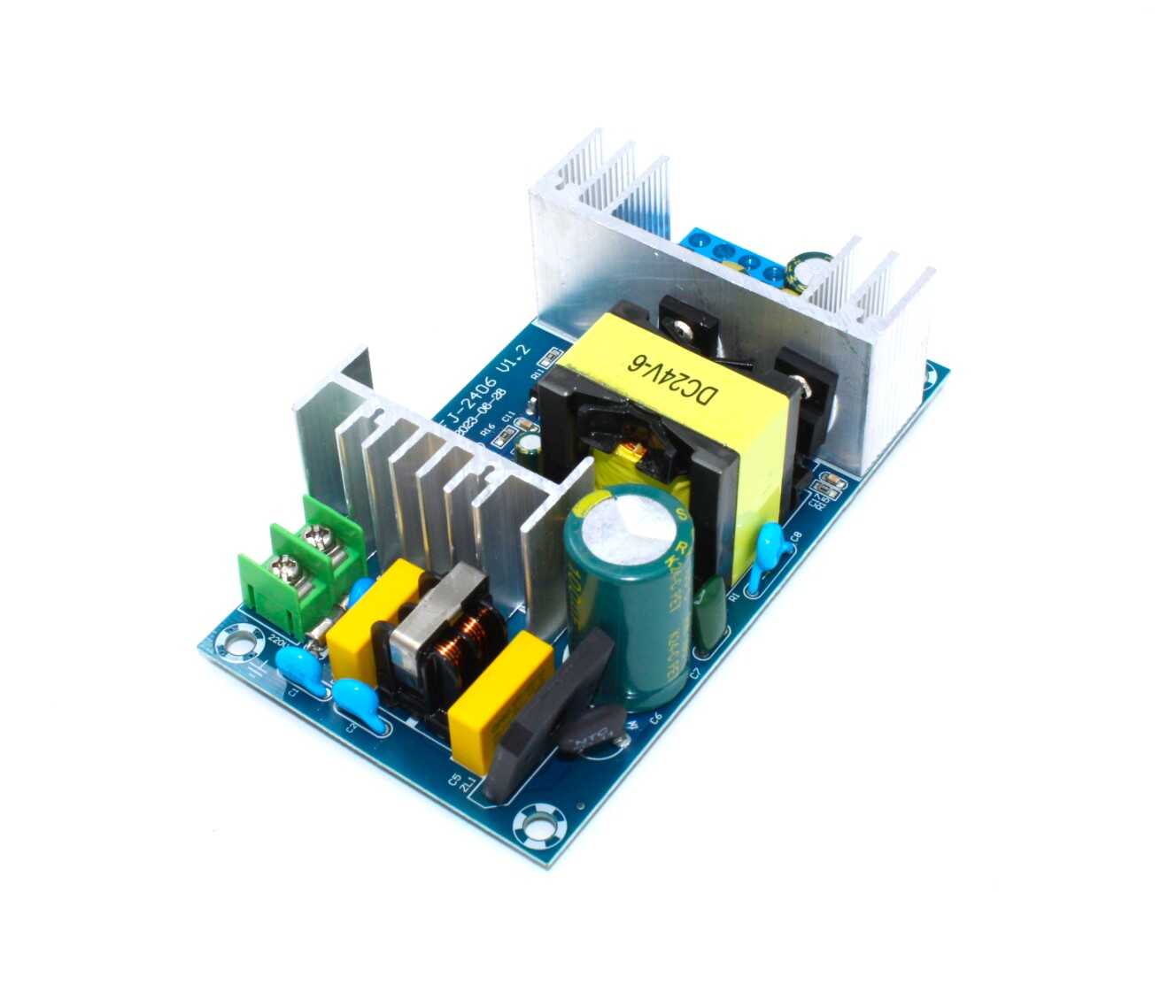
150W AC-DC Buck Converter 100V-240V to 24V 6A-9A
High-power step-down module ideal for industrial projects. Takes AC mains and delivers stable 24V DC.
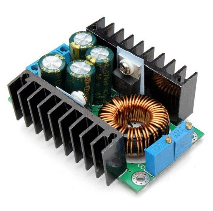
300W 10A DC-DC Step-down Buck Converter Adjustable
Adjustable constant voltage/current module for DIY power supplies, battery charging, and LED projects. Up to 300W output.
Practical Design Tips and Component Selection
Building your own buck-boost converter from scratch requires careful component selection. Here are the most important considerations:
Inductor Selection
The inductor is the heart of the converter. Key specs:
- Inductance value (L): Higher inductance = lower ripple current but slower transient response. For a 100 kHz converter, 10–47 µH is typical.
- Saturation current rating: Must exceed your peak inductor current by at least 20%. A saturating inductor dramatically reduces efficiency and can damage MOSFETs.
- DCR (DC resistance): Lower is better. This is the main source of conduction losses in the inductor.
- Core material: Shielded ferrite cores (e.g., Bourns SRR series) generate less EMI than unshielded iron powder cores.
MOSFET Selection
For the switching elements, choose MOSFETs with:
- Low Rds(on) — reduces conduction losses at rated current
- Gate charge (Qg) compatible with your driver — lower Qg = faster switching but more gate drive current needed
- Adequate Vds rating — typically 1.5× the maximum input voltage
Output Capacitor Selection
Use low-ESR capacitors (ceramic or polymer electrolytic) to minimise output ripple. The output ripple voltage is approximately: ΔVout ≈ ΔIL / (8 × f × Cout). For a 1% ripple on 5V output at 200 kHz, you’d need around 10–22 µF ceramic capacitors.
Controller IC Recommendations
- LM5175 (TI): Wide input 4-switch buck-boost, 60V input, high performance
- TPS63020 (TI): 1.8–5.5V input/output, up to 2A, perfect for Li-Ion battery projects
- LTC3780 (Analog Devices): High efficiency, 4–30V input, automotive grade
- XL6009: Budget-friendly Chinese IC, wide availability in Indian markets, handles up to 40V
PCB Layout Best Practices
Switching converters are sensitive to PCB layout. Always:
- Keep the high-current switching loop (input cap → MOSFET → inductor → output cap) as short and wide as possible
- Place input and output bulk capacitors physically close to the IC
- Route the feedback trace away from switching nodes to avoid noise pickup
- Use a solid ground plane; split AC and DC ground planes if possible
- Add a snubber RC network across the freewheeling diode if using hard-switching topology
Ready-Made Modules for Quick Projects
For prototyping and hobbyist projects, ready-made buck converter modules from Zbotic are the fastest way to get started. You don’t need to worry about component selection, PCB layout, or inductor sizing — just wire it up and adjust the output voltage with a potentiometer.
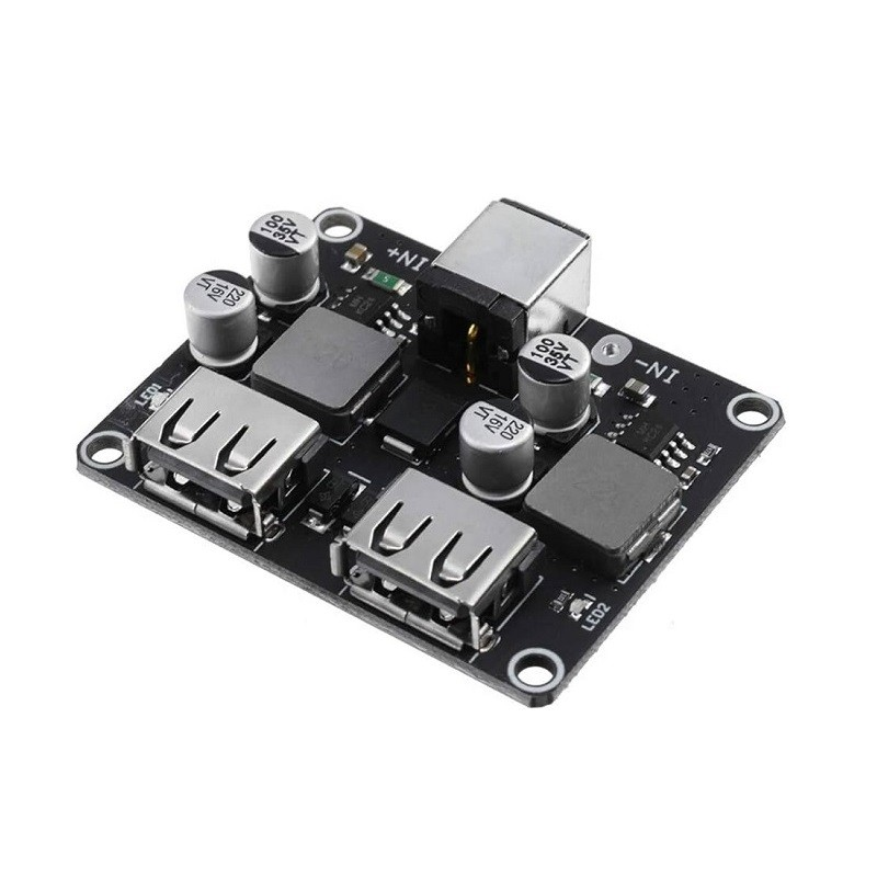
2 Channel USB QC3.0 QC2.0 DC-DC Buck Converter Charging Module
Step down from 6–32V to USB fast charging output. Perfect for vehicle-mounted chargers and power bank builds.
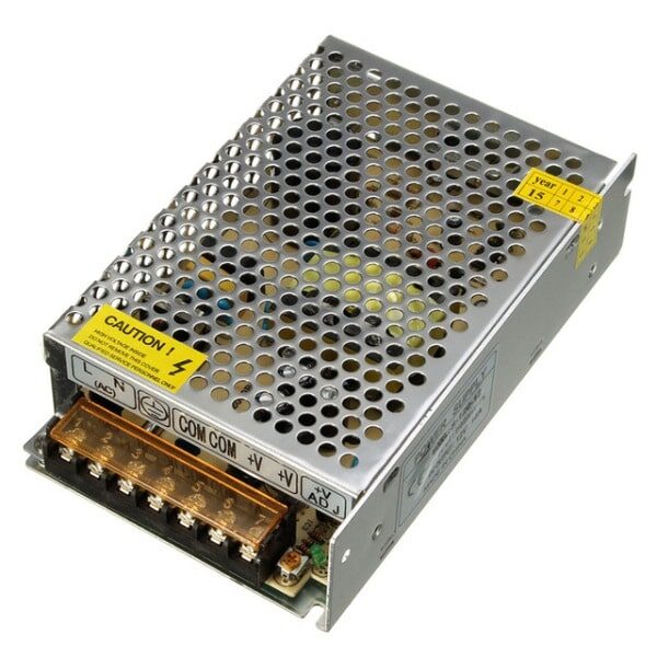
12V 10A SMPS – 120W DC Metal Power Supply
Reliable 120W SMPS for benchtop and industrial use. Ideal input source for buck-boost converter experiments.
When using ready-made modules, keep these tips in mind:
- Always check the maximum input voltage before connecting — exceeding it even briefly can destroy the IC
- Add an input fuse rated at 1.5× maximum input current for protection
- Modules with displays (voltmeter + ammeter) are worth the small premium for easy debugging
- Heatsink or active cooling is needed if running at more than 60% of rated power continuously
Buck-Boost vs Buck vs Boost: Choosing the Right One
| Parameter | Buck | Boost | Buck-Boost |
|---|---|---|---|
| Output vs Input | Vout < Vin always | Vout > Vin always | Vout < or > Vin |
| Complexity | Low | Low | Medium–High |
| Efficiency | 92–97% | 88–95% | 85–93% |
| Cost | Lowest | Low | Higher |
| Best for | Fixed higher input, fixed lower output | Fixed lower input, fixed higher output | Variable input crossing output voltage |
The decision tree is simple: start with a buck or boost if your input/output relationship is fixed. Graduate to a buck-boost only when the input voltage range crosses the desired output voltage. The added complexity and cost are only justified when necessary.
Frequently Asked Questions
Q1: Can a buck-boost converter work with both AC and DC input?
No — buck-boost converters work with DC input only. For AC input, you need a rectifier and filter stage first (which is what an SMPS does). The 150W AC-DC module listed above includes this front-end rectification built in.
Q2: What is the typical efficiency of a buck-boost converter?
Modern synchronous buck-boost converters achieve 88–93% efficiency at rated load. Efficiency drops at very light loads (below 10% of rated) and at very heavy loads near the thermal limit. The efficiency is typically a few percent lower than a pure buck or boost converter due to the additional switching elements involved.
Q3: Can I use a buck-boost converter to charge Li-Ion batteries?
Yes — this is one of the most popular applications. You need a buck-boost converter with constant-current (CC) and constant-voltage (CV) capability. Many dedicated battery charger ICs (like the BQ25896 or CN3791) use buck-boost topology internally. For DIY projects, adjustable modules with CC/CV display panels work well.
Q4: What causes output voltage ripple in a buck-boost converter?
Ripple is caused by the switching nature of the converter. During each switching cycle, current in the inductor ramps up and down, creating a small AC component on the output. This is reduced by: larger output capacitance, lower inductor ripple current (larger inductance), and higher switching frequency. A well-designed converter keeps ripple below 1% of output voltage.
Q5: What’s the difference between synchronous and non-synchronous buck-boost converters?
In a non-synchronous converter, a diode handles the freewheeling current path. In a synchronous converter, a MOSFET replaces the diode. Since MOSFETs have much lower voltage drop than diodes, synchronous converters are significantly more efficient — especially at high currents where diode losses dominate. Most modern module designs use synchronous topology.
Ready to Build Your Power Supply Project?
Zbotic stocks a range of DC-DC converter modules, SMPS units, and all the passive components — inductors, capacitors, MOSFETs — you need to build or prototype power electronics circuits. Browse our Electronics Components collection and get fast delivery across India.


Add comment