
Transistors are among the most common components on any circuit board, and they fail more often than people realise — sometimes from overcurrent, sometimes from heat, sometimes just from static discharge. Knowing how to test a transistor with a multimeter is an essential skill for any electronics hobbyist, repair technician, or engineer. In 5–10 minutes you can determine whether a transistor is good, shorted, open, or degraded — and avoid wasting time troubleshooting the rest of a circuit when the transistor is the root cause.
This guide covers BJT (Bipolar Junction Transistor) testing for both NPN and PNP types, explains what your readings mean, and also shows you how to check gain (hFE) and identify unknown transistor pinouts.
What You Will Need
- A digital multimeter (DMM) with diode test mode (this is the key mode for transistor testing)
- The transistor you want to test (removed from circuit for accurate results)
- The transistor’s datasheet (optional but helpful for pin identification)
Almost any digital multimeter with a diode test symbol (the triangle with a bar) will work. You do not need an expensive meter — even budget ₹300 multimeters work perfectly for this test.
Quick Transistor Basics
A Bipolar Junction Transistor (BJT) has three terminals:
- Base (B): The control terminal — a small current into the base controls a larger current through the transistor.
- Collector (C): The main current path (positive terminal for NPN, negative for PNP).
- Emitter (E): The output terminal (negative for NPN, positive for PNP).
Internally, a transistor is two back-to-back diodes: a Base-Emitter diode and a Base-Collector diode. This is what makes the diode test method work.
For an NPN transistor: both diodes point away from base (base is the P-type anode). The Collector-Emitter junction conducts only when the base is sufficiently forward-biased.
For a PNP transistor: both diodes point toward the base (base is the N-type cathode).
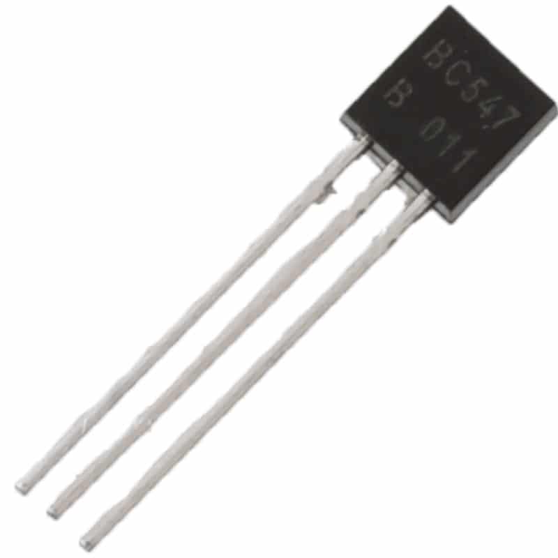
BC547 NPN 100mA Transistor TO-92 (Pack of 10)
Popular NPN transistor — ideal for practising transistor testing techniques and for switching and amplifier circuits.
Step 1: Identify the Transistor Pins
Using the Datasheet
Search the transistor part number (e.g. BC547, 2N2222, 2N3904) and open its datasheet. The pinout diagram will clearly label E, B, C. For TO-92 package transistors like BC547, looking at the flat face with the leads pointing down: left = Collector, middle = Base, right = Emitter.
Common Pinouts for Popular Transistors
| Transistor | Type | Package | Pinout (flat face, left→right) |
|---|---|---|---|
| BC547/BC548/BC549 | NPN | TO-92 | C – B – E |
| BC557/BC558 | PNP | TO-92 | C – B – E |
| 2N2222 | NPN | TO-92 | E – B – C |
| 2N3904 | NPN | TO-92 | E – B – C |
| TIP31/TIP41 | NPN | TO-220 | B – C – E |
Identifying Pins with the Multimeter (Unknown Transistor)
If you don’t have the datasheet, you can identify the base, type (NPN/PNP), and polarity using only the diode test mode:
- Set your multimeter to diode test mode.
- Probe each pair of legs (6 combinations for 3 pins) in both polarities (12 total tests).
- The pin that shows a forward voltage drop (0.5–0.8 V) to BOTH other pins (in the same probe orientation) is the Base.
- If base is the anode (red probe on base gives both drops): it is an NPN transistor.
- If base is the cathode (black probe on base gives both drops): it is a PNP transistor.
- Among C and E, the junction with higher forward voltage (usually 0.6–0.7 V) is typically Base-Emitter; the slightly lower reading is Base-Collector — though the difference is small and varies by transistor.
Step 2: Testing an NPN Transistor
Set your multimeter to diode test mode. The diode symbol looks like a triangle pointing right with a vertical bar at the tip.
Test 1: Base-Emitter Junction (Forward)
- Place the red probe (positive) on the Base.
- Place the black probe (negative) on the Emitter.
- Expected reading: 0.55–0.70 V (silicon junction forward voltage drop)
Test 2: Base-Emitter Junction (Reverse)
- Place the black probe on the Base.
- Place the red probe on the Emitter.
- Expected reading: OL (overload / open) — the junction is reverse-biased, no conduction.
Test 3: Base-Collector Junction (Forward)
- Place the red probe on the Base.
- Place the black probe on the Collector.
- Expected reading: 0.55–0.70 V
Test 4: Base-Collector Junction (Reverse)
- Place the black probe on the Base.
- Place the red probe on the Collector.
- Expected reading: OL (open)
Test 5: Collector-Emitter (Both Directions)
- Red on Collector, black on Emitter → Expected: OL
- Red on Emitter, black on Collector → Expected: OL
A good NPN transistor should pass all six of these tests. Any deviation indicates a fault.
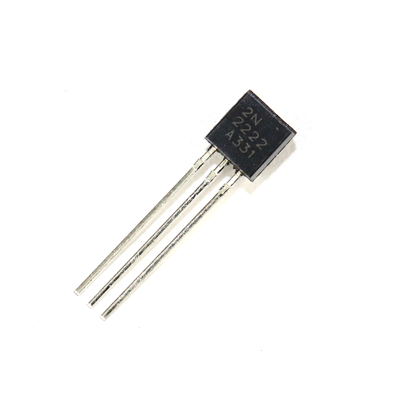
2N2222 NPN Transistor (Pack of 20)
A versatile NPN transistor for switching and amplifier projects — great to have on hand for testing and replacement.
Step 3: Testing a PNP Transistor
The PNP test is identical to NPN but with the probe polarity reversed for the diode junction tests.
Test 1: Base-Emitter Junction (Forward for PNP)
- Place the black probe on the Base.
- Place the red probe on the Emitter.
- Expected: 0.55–0.70 V
Test 2: Base-Emitter Junction (Reverse for PNP)
- Red on Base, Black on Emitter.
- Expected: OL
Test 3: Base-Collector Junction (Forward for PNP)
- Black probe on Base, red probe on Collector.
- Expected: 0.55–0.70 V
Test 4: Base-Collector Junction (Reverse for PNP)
- Red on Base, black on Collector.
- Expected: OL
Test 5: Collector-Emitter
- Both directions should read OL.
Step 4: Checking hFE (Gain) with Multimeter
Many digital multimeters include a dedicated hFE socket — a small port labelled “hFE” or “TRANS” with holes labelled E, B, C for both NPN and PNP. This feature measures the transistor’s current gain (hFE or β — the ratio of collector current to base current).
How to Use the hFE Socket
- Set the multimeter to hFE mode.
- Identify whether your transistor is NPN or PNP.
- Insert the transistor legs into the correct holes in the NPN or PNP socket section, matching E/B/C labels.
- Read the displayed value — this is the hFE (DC current gain, also called beta or β).
What is a Good hFE Reading?
- BC547: hFE typically 110–800 (the datasheet grades it into A/B/C groups)
- 2N2222: hFE typically 75–300 at low collector current
- BC557: hFE typically 125–500
If the hFE reads very low (e.g. 5–20 when it should be 100+), the transistor is degraded — it may still switch on/off but will not amplify well. Replace it.
Note: the multimeter hFE reading is at a fixed, low test current (usually 100 µA base current). Actual hFE in your circuit may differ with different currents — always cross-check with the datasheet.

LCR-T4 12864 LCD Transistor Tester (Resistance, Capacitance, ESR, SCR)
Auto-identifies transistor type, pinout, and hFE — saves time over manual multimeter testing and works on MOSFETs, diodes, capacitors too.
Understanding Your Results
Test Results Summary
| Measurement | NPN Good | Indicates Fault If |
|---|---|---|
| B→E (forward) | 0.55–0.70 V | OL = open junction; 0.000 = shorted |
| E→B (reverse) | OL | Any voltage = leaky junction |
| B→C (forward) | 0.55–0.70 V | OL = open; 0.000 = shorted |
| C→B (reverse) | OL | Any voltage = leaky/shorted |
| C↔E (both directions) | OL both ways | Low resistance or 0 V = collector-emitter short (most common failure) |
Most Common Failure: Collector-Emitter Short
The most frequent transistor failure mode is a collector-emitter short circuit. When this happens, the transistor conducts maximum current permanently regardless of base voltage — acting like a closed switch or dead short. On a power transistor that was overloaded, you will often read near-zero resistance between C and E in both directions. This is always a dead transistor.
Testing Transistors In-Circuit
Ideally, always remove the transistor from the circuit before testing. However, if desoldering is not practical:
- Power off the circuit completely before testing.
- In-circuit, parallel components (resistors, other semiconductors) create alternate current paths that can give false readings.
- If you measure a forward voltage drop of 0.4 V instead of 0.6 V on a junction, parallel resistors may be pulling the reading down — this does not necessarily mean the junction is bad.
- A collector-emitter short reading in-circuit is still reliable — if C-E reads near zero, the transistor is almost certainly shorted.
- Use a component tester (like the LCR-T4) for more reliable in-circuit estimates when desoldering is not possible.
Using a Component Tester
A dedicated component tester (like the LCR-T4 or Mega328 transistor tester) is far faster and more informative than a multimeter for transistor testing. You simply plug the transistor into the ZIF socket (any order — the tester auto-identifies pins), press the button, and within 2 seconds the display shows:
- Component type (NPN BJT, PNP BJT, MOSFET, JFET, diode, etc.)
- Pin identification (which pin is E, B, C)
- hFE value at the test current
- Base-emitter voltage (Vbe)
This eliminates the manual 12-measurement process and is invaluable when sorting unknown components from a mixed bin.
Common Transistor Failure Modes
- Collector-Emitter short: Most common. Caused by overcurrent, voltage spikes, or overheating. C-E reads ~0 Ω. Replace the transistor.
- Open Base-Emitter junction: Usually from ESD. B-E reads OL in both directions. Transistor won’t turn on at all.
- Leaky junctions: Reverse-biased junction shows small voltage (50–300 mV). Caused by excessive reverse voltage or aging. Results in high leakage current and unstable bias in amplifier circuits.
- Degraded hFE: Gain drops from 200 to 20. Transistor still switches but amplification is poor. Common in transistors run continuously at high temperatures.
- Thermal runaway damage: Transistor tested at room temperature may seem good but fails at operating temperature. Use a heat gun gently on the transistor while monitoring hFE — a sharp gain drop with heat suggests thermal damage.
Frequently Asked Questions
Can I test a transistor without removing it from the circuit?
You can get rough indications in-circuit, but accurate testing requires removing the transistor. Parallel components — especially base bias resistors and collector load resistors — distort diode test readings. A collector-emitter short is still detectable in-circuit, but open junctions may be masked by parallel paths.
My multimeter shows 0.000 V between B and E. Is the transistor shorted?
Yes, a reading of 0.000 V (or very near zero) in forward bias means the junction is short-circuited. The transistor is faulty and must be replaced.
My multimeter shows OL in both directions on all three junctions. What does it mean?
All open readings typically mean the transistor has completely failed open — all junctions are open-circuited. This can happen from ESD damage or severe overcurrent that physically melts the bond wires inside.
What forward voltage should a germanium transistor show?
Germanium transistors (common in vintage audio equipment — types like AC127, OC71) have a lower forward junction voltage of approximately 0.20–0.35 V, compared to 0.55–0.70 V for silicon. Testing method is identical, just expect lower voltage readings.
Can I test MOSFETs the same way?
Not exactly. MOSFETs have a different structure. In diode test mode you will see a body diode between drain and source. However, MOSFETs are better tested with a dedicated MOSFET tester or component tester (LCR-T4 handles MOSFETs automatically). The gate is voltage-controlled, not current-controlled, so the test method differs from BJTs.
How do I know if a transistor is NPN or PNP without a datasheet?
Use the pin-finding method: in diode test mode, find the pin that shows a forward voltage drop (0.5–0.7 V) when the red probe is placed on it and both other pins are probed with the black probe — that pin is the base of an NPN transistor. If you need black on the mystery pin to get drops to both others, it is a PNP base. The red probe connects to the anode of a forward-biased junction, so: red on base = NPN, black on base = PNP.
Need transistors for your next project? Zbotic.in stocks BC547, 2N2222, and more — available in convenient packs. Shop at zbotic.in for quality components delivered fast across India.


Add comment