
The worm gear motor’s self-locking property is one of the most underappreciated features in the robotics and automation toolkit. While most gear motors will backdrive (rotate backward) when an external force is applied, a properly designed worm gear motor holds its position with zero power — like a physical latch built into the drivetrain. This guide explains the mechanics behind self-locking, when it is useful, when it is a problem, and which real-world applications benefit most from this unique behaviour.
Worm Gear Basics: How the Mechanism Works
A worm gear drive consists of two components: a worm (a helical screw-shaped gear on the input shaft, driven by the motor) and a worm wheel (a spur or helical gear on the output shaft that meshes with the worm’s threads). As the worm rotates, its threads push the teeth of the worm wheel sideways, creating output rotation at 90° to the input shaft.
This perpendicular configuration provides several advantages over parallel-shaft gear trains:
- Very high reduction ratios in a single stage (typically 5:1 to 100:1)
- Compact, right-angle output configuration
- Inherently smooth, low-shock power transmission
- And most critically — potential for self-locking (back-driving prevention)
The geometry of worm gears means the worm can always drive the wheel forward, but the reverse is not automatically true — whether the wheel can backdrive the worm depends entirely on the lead angle and friction coefficient of the gear surfaces.
Self-Locking Explained: The Physics
Self-locking occurs when the friction forces at the worm-wheel mesh are large enough to prevent the worm wheel from rotating the worm backward. In mechanical engineering terms, the system is self-locking when:
tan(lead angle) < µ (coefficient of friction)
Where µ is the friction coefficient between the worm and wheel (typically 0.05–0.15 for steel-on-bronze lubricated pairs). When the lead angle is small (steep helix, many thread starts per tooth), the geometry essentially creates a wedging action — any load on the output shaft drives the gear tooth deeper into the worm thread rather than rotating it.
Think of it like a screw and nut: you can rotate the screw to move the nut linearly, but pressing on the nut won’t spin the screw — the steep thread angle and friction make backdrive impossible without applying far more force than the mechanism was designed for.
Lead Angle: The Key Parameter
Lead angle is the angle between the worm thread and a plane perpendicular to the worm axis. It directly determines whether self-locking occurs:
| Lead Angle | Self-Locking? | Efficiency (%) | Typical Gear Ratio |
|---|---|---|---|
| < 5° | Almost certain | 20–35% | 50:1 – 100:1 |
| 5°–15° | Likely (verify with µ) | 35–65% | 20:1 – 50:1 |
| 15°–25° | Marginal / unreliable | 65–80% | 10:1 – 20:1 |
| > 25° | No — backdrives freely | 80–95% | < 10:1 |
Practical note: Most low-cost hobby worm gear motors with ratios above 30:1 are reliably self-locking under normal conditions. However, self-locking should never be relied upon for safety-critical applications (such as holding a load over a person) because vibration, temperature changes, and lubrication condition changes can reduce friction enough to allow slow backdrive.
Efficiency Trade-offs
Self-locking comes at a cost: worm gear drives are significantly less efficient than parallel-shaft spur or helical gear drives. At a 50:1 ratio, a worm gear drive may only be 40% efficient — meaning 60% of input power is dissipated as heat in the gear mesh. For comparison, a planetary gear drive at the same ratio achieves 90%+ efficiency.
This has important implications for battery-powered applications:
- A 10 W motor driving a load through a 40% efficient worm drive delivers only 4 W of useful mechanical output
- Motor and gearbox run hotter under equivalent loads compared to spur or planetary drives
- For continuous-run applications, a worm drive requires a significantly larger motor than a planetary drive
However, for intermittent applications (a door that opens and closes a few times per day, a positioning stage that moves occasionally), the efficiency penalty is irrelevant — the energy consumed per cycle is still tiny, and the self-locking benefit is enormous.
Top Applications for Self-Locking Worm Gear Motors
The self-locking property makes worm gear motors the ideal choice for any application where the actuator must hold its position without drawing continuous power. This covers a surprisingly wide range of systems:
Door Openers & Window Actuators
Automatic door openers and motorised window actuators are perhaps the most common consumer application. The motor opens or closes the door/window, then power is cut — the worm drive holds the position against wind pressure, gravity, or accidental human force without consuming any electricity.
For a motorised door lock project with Arduino:
- Use a 12 V worm gear motor at 30–60 RPM (depends on mechanism geometry)
- Drive with L298N module (adequate for 12 V, handles 2 A)
- Use a limit switch at each end of travel to cut power when fully open/closed
- The self-locking worm drive handles the “stay closed” requirement without a solenoid latch
This approach is far simpler than spur-gear solutions that require a separate electromagnetic brake or latch mechanism.
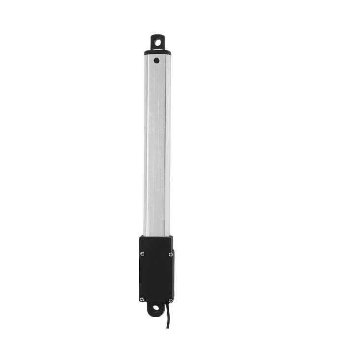
LA-T8-100 Linear Actuator for Doors & Windows
A compact 6V linear actuator using an internal worm-screw mechanism — self-locking by design, perfect for automated window openers and small door actuators.
Robotic Arm Joints & Pan-Tilt Heads
Robotic arm joints driven by worm gear motors hold their position when power is removed — critical for battery-powered arms that must conserve energy while holding a pose. A servo motor holds position by constantly drawing current to fight against gravity; a worm-driven joint holds for free.
Camera pan-tilt heads similarly benefit: the camera stays pointed at a subject even when the pan/tilt motors are switched off, with no drift. This is why professional broadcast pan-tilt heads often use worm drives internally.
For DIY robotic arm joints:
- Choose a worm gear motor with gear ratio matched to the torque needed (consider arm length and payload)
- A 50:1 ratio motor with 5 kg·cm output torque can hold a 200g payload at 250mm reach
- Add a potentiometer or encoder for position feedback — worm drives don’t provide inherent feedback
Linear Motion Stages & Jacks
Worm gear motors combined with a leadscrew nut create a self-locking linear actuator. This is the operating principle of scissor jacks, laboratory positioning stages, and microscope focus drives. The linear position is maintained without power, and the high gear ratio provides the force multiplication needed to lift heavy loads.
A 12 V worm gear motor at 5 RPM with a 2 mm pitch leadscrew advances the load 10 mm/minute — very slow, very controlled, and self-locking at every position.
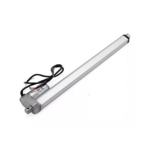
DC12V 500MM 2000N Linear Actuator
A heavy-duty 2000N force linear actuator with internal screw-worm mechanism — self-locking, suitable for solar panel tilting, hydraulic-free lifts, and industrial jigs.
Conveyors & Lifting Mechanisms
A conveyor loaded with goods will tend to backdrive its motor when power is cut — gravity or the load’s inertia pulls the belt backward. A worm gear drive prevents this without a brake, making it the traditional choice for conveyor drive systems and chain-driven goods lifts.
In hobbyist settings, worm gear motors are used in:
- Automated seed dispensers and pill dispensers (portion control via precise rotation)
- Coin-operated vending mechanisms (single-rotation indexing)
- Lab stirrers and rotisserie mechanisms (constant torque against gravity)
- Solar panel sun-tracking systems (hold panel angle through the night)
When NOT to Use a Self-Locking Motor
The self-locking and low-efficiency properties make worm gear motors a poor choice in several scenarios:
- High-speed, continuous-duty applications: The low efficiency means the motor and gearbox run hot. For fans, pumps, or spindles, use a direct-drive or spur-gear motor.
- Back-drivable applications: If you need the output shaft to be manually repositionable (e.g., manually adjusting a display stand), a self-locking drive prevents this. Use a helical or planetary gear motor instead.
- Weight-sensitive designs: Worm gear drives are heavier and bulkier than equivalent-ratio planetary drives for the same power output.
- High-cycle precision applications: The sliding contact in worm gear meshes causes wear faster than rolling contact in helical gears. For applications with millions of duty cycles, investigate alternative topologies.
Selecting a Worm Gear Motor
When choosing a worm gear motor, specify the following parameters in order:
- Output torque (kg·cm or N·m): Calculate the load torque including friction and safety margin (≥2×).
- Output RPM: Determines linear speed or rotational rate at the application. Lower RPM = higher reduction = more likely self-locking.
- Voltage: Match to your power supply (6 V, 12 V, or 24 V are standard).
- Shaft type: D-shaft for direct coupling; round shaft for flexible couplers.
- Mounting: Flange mount, foot mount, or shaft-mount variants exist for different mechanical integrations.
- Duty cycle: If the motor runs continuously, factor in the low efficiency — you may need a larger frame size.
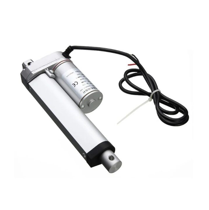
Linear Actuator 100MM, 1500N, 12V
A self-locking screw-driven actuator delivering 1500N force across 100mm stroke — ideal for robotic lifting arms, adjustable fixtures, and automated tooling.
Control & Driver Considerations
Driving a worm gear motor is identical to driving any DC motor — use a motor driver IC (L298N, TB6612FNG, or DRV8833 depending on current requirements) with PWM speed control and direction control.
Key considerations specific to worm gear motors:
- Starting torque: Worm drives have higher static friction than running friction. Ensure your driver can supply stall current at startup, especially when the load is applied before the motor is energised.
- Abrupt direction reversal: Avoid instantaneous direction reversal without a brief stop. The inertia of the output load combined with the worm drive’s tendency to jam momentarily can spike current to 3–5× normal.
- Position sensing: Add a limit switch or potentiometer at the output shaft — the worm drive holds position but doesn’t tell the controller where it is. Without position feedback, the motor can’t know it has reached the target.
- Braking: Since the drive is self-locking, you don’t need active braking. Simply cutting power (coasting) leaves the shaft locked in place.
Frequently Asked Questions
Is all worm gear motors self-locking?
No — self-locking depends on the lead angle and friction coefficient of the specific gear pair. Motors with low gear ratios (under 10:1) typically have lead angles too steep for self-locking. Most worm gear motors with ratios of 30:1 or higher are self-locking under typical conditions, but always verify with the manufacturer’s datasheet or test empirically.
Can I use a worm gear motor to hold a heavy load safely?
Self-locking worm drives can hold loads passively, but should not be the sole safety mechanism for loads over people or in life-safety applications. Friction-based locking can release with vibration, temperature change, or lubrication. Use a separate mechanical latch or brake for safety-critical vertical holding applications.
Why is my worm gear motor running hot?
Low efficiency (40–60%) means worm drives dissipate significant heat even under normal load. If the motor is significantly hotter than expected, check: (1) that the load doesn’t exceed the rated torque, (2) that the duty cycle allows cooling between operations, and (3) that the gearbox is lubricated — dry gears increase friction and heat generation dramatically.
How do I calculate if my worm gear motor will self-lock?
The condition is: tan(lead angle) < µ. Lead angle = arctan(lead / (π × worm pitch diameter)). For a conservative estimate, use µ = 0.05 (well-lubricated steel-on-bronze). Most gear ratios above 20:1 satisfy this condition with comfortable margin.
Can I backdrive a worm gear motor manually for emergency repositioning?
A self-locking worm drive cannot be backdriven by normal hand force — this is the point of self-locking. For applications requiring occasional manual override, choose a worm drive with a higher lead angle (lower ratio, e.g., 10:1 or less) or add a manual clutch mechanism to disengage the worm from the wheel when needed.


Add comment