
CMOS vs TTL Logic: Speed, Power and Voltage Comparison
When designing any digital circuit, one of the first questions you face is which logic family to use. The CMOS vs TTL logic debate has been central to electronics engineering for decades, and understanding the differences is essential for every maker, student, and professional in India working with microcontrollers, discrete logic ICs, or interfacing different systems together. This comprehensive guide explains the key differences in speed, power consumption, voltage levels, noise margins, and practical use cases — so you can choose the right logic family every time.
What Is TTL Logic?
TTL stands for Transistor-Transistor Logic. It was the dominant digital logic family from the late 1960s through the 1980s, defined by the 74xx series of ICs that you still find in use today. TTL gates are built using bipolar junction transistors (BJTs) — specifically multiple-emitter NPN transistors — which explains the "transistor-transistor" name.
The original 74xx series (now called standard TTL) has largely been superseded by improved sub-families:
- 74Lxx (Low Power TTL): Reduced power draw, slower speed.
- 74Sxx (Schottky TTL): Much faster due to Schottky diode clamping that prevents saturation. Typical propagation delay ~3 ns.
- 74LSxx (Low Power Schottky): Best balance of speed and power in classic TTL. Most common "TTL" ICs sold today.
- 74ALSxx (Advanced Low Power Schottky): Faster and lower power than 74LS.
- 74Fxx (Fast TTL): High speed, used in demanding applications.
All TTL families operate from a 5V supply and cannot tolerate supply voltages outside this range. The input current requirements (TTL inputs sink current) place a load on driving sources — something that matters when interfacing with other logic families.
What Is CMOS Logic?
CMOS stands for Complementary Metal-Oxide-Semiconductor. Unlike TTL, CMOS gates are built from pairs of complementary MOSFET transistors — one N-channel and one P-channel — connected in a push-pull arrangement. This complementary structure is the key to CMOS’s most celebrated advantage: near-zero static power consumption.
The main CMOS logic families:
- 4000 series (CD4xxx / MC14xxx): Original CMOS, operates from 3V to 18V. Very slow (µs propagation delays), but extremely low power. Still widely used for battery-powered applications where speed is irrelevant.
- 74HCxx (High-Speed CMOS): CMOS fabrication with TTL-compatible pinouts. 5V supply, propagation delay ~8 ns, very low static power.
- 74HCTxx (High-Speed CMOS, TTL-input compatible): Same as HC but with TTL-compatible input voltage thresholds. The critical choice when interfacing with 5V TTL logic.
- 74ACxx / 74ACTxx (Advanced CMOS): Even faster than HC, ~5 ns propagation delay.
- 74VHCxx (Very High Speed CMOS): Fast, 2.0V to 5.5V supply. Used in modern 3.3V systems.
- 74LVCxx (Low Voltage CMOS): 1.65V to 3.3V supply. Standard for modern 3.3V microcontrollers and FPGAs.
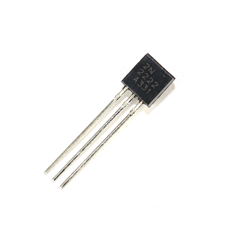
2N2222 NPN Transistor (Pack of 20)
The 2N2222 NPN BJT is the classic TTL-era transistor. Understanding how it works gives you the foundation to understand TTL gate internals. Essential for discrete logic experiments.
Voltage Levels and Logic Thresholds
Understanding voltage levels is the most practically important aspect of CMOS vs TTL for circuit design. Here is the comparison for standard 5V supply:
| Parameter | Standard TTL (74LS) | CMOS (74HC) @5V | CMOS 4000 @5V |
|---|---|---|---|
| VOH min (output high) | 2.7V | 4.9V | 4.95V |
| VOL max (output low) | 0.5V | 0.1V | 0.05V |
| VIH min (input high) | 2.0V | 3.5V | 3.5V |
| VIL max (input low) | 0.8V | 1.0V | 1.5V |
| Supply voltage range | 4.75V – 5.25V | 2V – 6V | 3V – 18V |
The critical problem: A TTL output drives HIGH at minimum 2.7V. A 74HC CMOS input requires HIGH at minimum 3.5V. That 2.7V TTL output may or may not be recognised as HIGH by a 74HC input — it falls in the undefined region. This is the #1 interfacing trap that catches beginners. The solution is to use 74HCT instead of 74HC — the HCT variant has TTL-compatible input thresholds (VIH = 2.0V), solving this problem.
Speed Comparison: Propagation Delay
Propagation delay (tpd) is the time from input change to output change — the fundamental speed metric for logic gates.
| Logic Family | Typical tpd | Max Clock Freq |
|---|---|---|
| 4000 series CMOS | 125 ns | ~4 MHz |
| 74LS TTL | 9 ns | ~55 MHz |
| 74S TTL (Schottky) | 3 ns | ~125 MHz |
| 74HC CMOS | 8 ns | ~80 MHz |
| 74AC CMOS | 5 ns | ~200 MHz |
| 74LVC CMOS | 4 ns | ~200+ MHz |
The key takeaway: 74HC CMOS is approximately as fast as 74LS TTL, while consuming far less power. Modern CMOS families (74AC, 74LVC) are significantly faster than any classic TTL family. The old idea that "TTL is fast, CMOS is slow" only applies if you are comparing against the ancient 4000 series.
Power Consumption: Static and Dynamic
This is where CMOS has its most decisive advantage. CMOS gates draw negligible current when static (not switching) because neither the PMOS nor NMOS transistor is fully on simultaneously. A 74HC gate at 5V draws only ~80 µA quiescent current. Compare this to a 74LS TTL gate that draws ~2 mA even when idle — 25× more.
However, CMOS is not always more power-efficient at high frequencies. Dynamic power consumption of a CMOS gate is:
P_dynamic = α × C_L × V_DD² × f
Where α is the switching activity factor, C_L is the load capacitance, V_DD is the supply voltage, and f is the switching frequency. At high frequencies, CMOS dynamic power can exceed TTL power. This is why modern processors run at low supply voltages (0.8V–1.0V) — the V_DD² term makes voltage reduction extremely effective.
Practical power comparison at 5V, 1 MHz:
- 74LS NAND gate: ~2.4 mW per gate (mostly static)
- 74HC NAND gate: ~1.7 mW per gate (mostly dynamic at 1 MHz)
- 74HC at 100 kHz: ~0.17 mW per gate — 14× less than 74LS
For battery-operated projects — Arduino running on a 9V battery, a sensor node on two AAA cells — CMOS is the only sensible choice. At low switching frequencies, CMOS power consumption is orders of magnitude lower than TTL.
Noise Margins and Immunity
Noise margin is the voltage difference between the guaranteed output level and the required input threshold — it is the circuit’s tolerance for electrical noise on signal lines.
For 74LS TTL at 5V:
– High noise margin: VOH(min) – VIH(min) = 2.7V – 2.0V = 0.7V
– Low noise margin: VIL(max) – VOL(max) = 0.8V – 0.5V = 0.3V
For 74HC CMOS at 5V:
– High noise margin: VOH(min) – VIH(min) = 4.9V – 3.5V = 1.4V
– Low noise margin: VIL(max) – VOL(max) = 1.0V – 0.1V = 0.9V
CMOS noise margins are 2–3× larger than TTL. This makes CMOS significantly more immune to noise, which is one reason it has displaced TTL in most modern applications. In noisy industrial environments, CMOS ICs are much more reliable.

0.1µF Ceramic Capacitor (Pack of 50)
Whether using CMOS or TTL, always decouple each IC with a 100nF ceramic capacitor between VCC and GND. This is the single most important practice for reliable digital circuit operation.
Interfacing CMOS and TTL Together
Real-world boards often mix logic families. Here is your interfacing guide:
TTL driving CMOS (same 5V supply)
Problem: TTL VOH(min) = 2.7V, 74HC VIH(min) = 3.5V — gap of 0.8V. Unreliable!
Solutions:
1. Use 74HCT instead of 74HC — HCT has TTL-compatible inputs (VIH = 2.0V). Preferred approach.
2. Add a pull-up resistor (4.7 kΩ to 5V) on the TTL output to pull it up to near 5V.
CMOS driving TTL (same 5V supply)
74HC VOH = 4.9V drives TTL VIH = 2.0V easily. 74HC VOL = 0.1V drives TTL VIL = 0.8V easily. No issues — CMOS driving TTL at the same voltage works fine.
3.3V CMOS to 5V TTL
3.3V GPIO (Arduino Due, ESP32, STM32) driving 5V TTL: 3.3V output may not reliably drive 5V TTL VIH = 2.0V — it usually works marginally. For robust interfacing, use a 74LVC245 level shifter (accepts 3.3V input, drives 5V output).
5V TTL to 3.3V CMOS
Never directly connect 5V TTL output to 3.3V CMOS input — the 5V will damage the 3.3V IC. Always use a level shifter: 74LVC245, TXB0108, or a simple resistor voltage divider (5V → 3.3V with 10 kΩ and 20 kΩ).

10CM Female To Female Breadboard Jumper Wires 2.54MM – 40Pcs
Perfect for prototyping CMOS and TTL logic circuits on a breadboard. Colour-coding your wires by voltage level (5V vs 3.3V) prevents accidental damage to CMOS ICs.
Which Logic Family Should You Use?
| Use Case | Recommended Family |
|---|---|
| Battery-powered, low speed | 4000B CMOS or 74HC |
| 5V Arduino interfacing | 74HC or 74HCT |
| Mixing 5V TTL with CMOS | 74HCT (TTL-input CMOS) |
| 3.3V ESP32/STM32 systems | 74LVC series |
| High-speed >100 MHz | 74AC or 74LVC |
| Legacy TTL replacement | 74LS or 74HCT |
| Wide supply voltage range | 4000B CMOS (3V–18V) |
Bottom line: For any new design in 2024, CMOS (specifically 74HC/HCT for 5V, 74LVC for 3.3V) is almost always the right choice. TTL is a legacy technology you will encounter in older equipment and textbooks, but CMOS dominates modern digital electronics from smartphones to microcontrollers.

0 Ohm 0.25W Carbon Film Resistor (Pack of 100)
Zero-ohm resistors are handy jumpers for PCB layouts connecting different logic sections. Pull-up resistors (4.7k–10k) are also essential for TTL-to-CMOS interfacing on the same board.
Frequently Asked Questions
Can I directly replace a 74LS TTL IC with a 74HC CMOS IC?
Usually yes for the same logical function, but watch the input voltage requirement. If the 74LS is being driven by another TTL output (VOH min = 2.7V), the 74HC input (VIH min = 3.5V) may not switch reliably. Use 74HCT as a direct drop-in replacement instead — it accepts TTL-level inputs and has the same pinout as 74LS.
Why do floating CMOS inputs cause problems?
CMOS inputs draw virtually no current, so floating inputs oscillate at undefined voltages between VIL and VIH — in the linear region where both PMOS and NMOS are partially on simultaneously. This causes continuous short-circuit current flow, excessive power consumption, and unpredictable output states. Always connect unused CMOS inputs to VCC (for logic high) or GND (for logic low) through a resistor.
What does "totem pole" output mean in TTL?
Standard TTL has a "totem pole" output — an upper NPN transistor (pulls output high) stacked above a lower NPN transistor (pulls output low). It actively drives both high and low states. This means you cannot wire-OR two TTL totem-pole outputs together — both trying to drive opposite states would cause a short circuit. Use open-collector outputs for wire-OR applications.
Is Arduino 5V CMOS or TTL?
The ATmega328P microcontroller used in Arduino Uno is a CMOS device running at 5V. Its digital I/O characteristics are CMOS-based: VOH typically ~4.8V, VOL typically ~0.2V. However, its input thresholds are roughly TTL-compatible (VIH ~3.0V, VIL ~1.5V). So Arduino plays well with both CMOS and TTL logic families at 5V.
What is the main advantage of 3.3V CMOS over 5V?
Lower supply voltage means dramatically lower dynamic power (P ∝ V²). At 3.3V vs 5V, dynamic power drops by (3.3/5)² = 44%. Modern processors and FPGAs go even lower (0.8V–1.2V core voltage) for the same reason. Additionally, 3.3V logic is directly compatible with modern microcontrollers like ESP32, STM32, and Raspberry Pi GPIO, avoiding level-shifting overhead.
Stock Up on Electronics Basics from Zbotic
From resistors and capacitors to transistors and prototype boards — Zbotic has all the discrete components you need for digital logic projects. Fast delivery across India, competitive INR pricing, and quality parts from trusted brands.


Add comment