
Mastering ESP32 UART serial GPS GSM hardware serial communication is one of the most valuable skills for any IoT engineer or hobbyist in India. The ESP32 microcontroller has three hardware UART peripherals (UART0, UART1, UART2), which means you can simultaneously talk to a GPS module for location data, a GSM module for cellular communication, and still keep UART0 free for your debug console — all without any software bit-banging overhead. This tutorial walks you through the entire process from wiring to production-grade code.
Understanding ESP32 UART Architecture
The ESP32 is built on a dual-core Xtensa LX6 processor and includes three hardware UART controllers: UART0, UART1, and UART2. Each UART can be remapped to almost any GPIO pin using the ESP32’s GPIO matrix — this is a significant advantage over the AVR-based Arduino boards where UARTs are fixed to specific pins.
Default pin assignments for the ESP32 DEVKIT board are:
| UART | Default TX | Default RX | Primary Use |
|---|---|---|---|
| UART0 | GPIO1 | GPIO3 | Debug/programming (USB) |
| UART1 | GPIO10 | GPIO9 | Flash memory (usually reserved) |
| UART2 | GPIO17 | GPIO16 | Free for user use |
In practice you should remap UART1 to safer GPIO pins (e.g., GPIO25/GPIO26) since GPIO9 and GPIO10 share the flash memory bus and can cause crashes on some modules. UART2 with its default GPIO16/GPIO17 is the safest choice for your first peripheral without any remapping.
Hardware Serial vs Software Serial
Software serial (bit-banging) on the ESP8266 is notoriously unreliable above 9600 baud and causes Wi-Fi interruptions because it disables interrupts during bit periods. The ESP32 with its three hardware UARTs has no such limitation. Each hardware UART has dedicated silicon with a 128-byte RX FIFO buffer and a hardware baud rate generator, so you can receive GPS NMEA sentences at 9600 baud and GSM AT commands at 115200 baud simultaneously without missing a single character.
The Arduino ESP32 core represents these as HardwareSerial objects: Serial (UART0), Serial1 (UART1), Serial2 (UART2). You initialise them using the begin(baudRate, config, rxPin, txPin) overload.
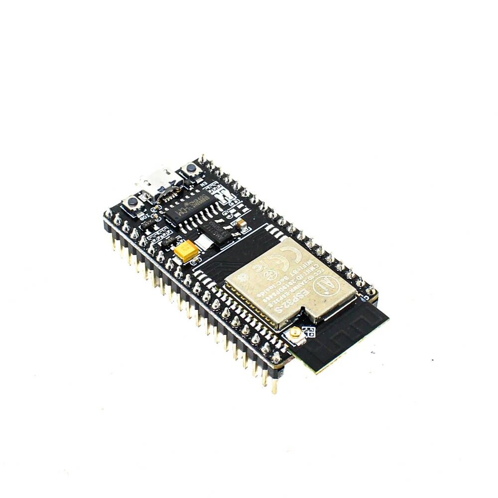
Ai Thinker NodeMCU-32S ESP32 Development Board – IPEX Version
A full-featured ESP32 development board with an IPEX antenna connector for enhanced range — ideal for GPS tracker and GSM projects.
Wiring a GPS Module (NEO-6M / NEO-8M)
The NEO-6M and NEO-8M GPS modules from u-blox are the most popular choices in India for hobbyist and professional projects. Both communicate over UART at 9600 baud by default and output standard NMEA 0183 sentences like $GPGGA, $GPRMC, and $GPGSA.
Wiring for ESP32 UART2 (no remapping needed):
- GPS VCC → ESP32 3.3 V (important: the module runs on 3.3 V, not 5 V)
- GPS GND → ESP32 GND
- GPS TX → ESP32 GPIO16 (UART2 RX)
- GPS RX → ESP32 GPIO17 (UART2 TX)
Note that you connect GPS TX to ESP32 RX and GPS RX to ESP32 TX — always cross the TX/RX lines. Many beginners trip up here. The GPS module’s TX line transmits data; your microcontroller’s RX line receives it.
In your Arduino sketch, initialise like this:
#include <TinyGPS++.h>

HardwareSerial GPSSerial(2);  // UART2
TinyGPSPlus gps;

void setup() {
  Serial.begin(115200);
  GPSSerial.begin(9600, SERIAL_8N1, 16, 17);  // RX=16, TX=17
}

void loop() {
  while (GPSSerial.available() > 0) {
    gps.encode(GPSSerial.read());
  }
  if (gps.location.isUpdated()) {
    Serial.printf("Lat: %.6f, Lon: %.6fn",
      gps.location.lat(), gps.location.lng());
  }
}
The TinyGPS++ library handles all the NMEA sentence parsing. It is available through the Arduino Library Manager and works perfectly with ESP32.
Wiring a GSM Module (SIM800L / SIM900)
The SIM800L is the most affordable GSM/GPRS module available in India, often found for under ₹400. It communicates via UART AT commands at 9600–115200 baud. The critical challenge with the SIM800L is power: it requires up to 2 A peak current during GSM registration and transmission bursts, which the ESP32’s 3.3 V pin cannot supply.
Power supply rules for SIM800L:
- Supply voltage: 3.4 V to 4.4 V (optimal: 4.0 V)
- Peak current: up to 2 A during transmission burst
- Use a dedicated LiPo battery or a high-current LDO regulator (not the ESP32’s onboard regulator)
- Add a 1000 µF capacitor across the SIM800L VCC and GND pins to buffer current spikes
Wiring for ESP32 UART1 remapped to safe pins:
- SIM800L VCC → 4.0 V dedicated supply (LiPo or buck converter output)
- SIM800L GND → common GND (shared with ESP32)
- SIM800L TX → ESP32 GPIO26 (UART1 RX, remapped)
- SIM800L RX → voltage divider → ESP32 GPIO25 (UART1 TX, remapped)
To initialise UART1 on custom pins:
HardwareSerial GSMSerial(1);  // UART1

void setup() {
  GSMSerial.begin(9600, SERIAL_8N1, 26, 25);  // RX=26, TX=25
  delay(3000);  // wait for SIM800L to register
  GSMSerial.println("AT");      // test communication
  delay(500);
  GSMSerial.println("AT+CMGF=1");  // SMS text mode
}
Arduino Code for Dual UART Operation
Running GPS and GSM simultaneously on two separate UART ports is straightforward because each HardwareSerial object manages its own buffer independently. Here is a complete dual-UART sketch that logs GPS position to a server via GSM:
#include <TinyGPS++.h>

HardwareSerial GPSSerial(2);   // UART2: GPS
HardwareSerial GSMSerial(1);   // UART1: SIM800L
TinyGPSPlus gps;

unsigned long lastSend = 0;
const unsigned long SEND_INTERVAL = 60000;  // 1 minute

void setup() {
  Serial.begin(115200);
  GPSSerial.begin(9600, SERIAL_8N1, 16, 17);
  GSMSerial.begin(9600, SERIAL_8N1, 26, 25);
  delay(3000);
  initGSM();
}

void initGSM() {
  GSMSerial.println("AT+CREG?");  // check registration
  delay(1000);
  GSMSerial.println("AT+CGATT=1");  // attach GPRS
  delay(2000);
  GSMSerial.println("AT+SAPBR=3,1,"Contype","GPRS"");
  delay(500);
  GSMSerial.println("AT+SAPBR=3,1,"APN","airtelgprs.com"");
  delay(500);
  GSMSerial.println("AT+SAPBR=1,1");
  delay(3000);
}

void sendGPSData(float lat, float lon) {
  GSMSerial.println("AT+HTTPINIT");
  delay(500);
  String url = "AT+HTTPPARA="URL","http://yourserver.in/track?lat="
               + String(lat, 6) + "&lon=" + String(lon, 6) + """;
  GSMSerial.println(url);
  delay(500);
  GSMSerial.println("AT+HTTPACTION=0");
  delay(5000);
  GSMSerial.println("AT+HTTPTERM");
}

void loop() {
  while (GPSSerial.available()) {
    gps.encode(GPSSerial.read());
  }
  if (gps.location.isValid() &&
      millis() - lastSend > SEND_INTERVAL) {
    sendGPSData(gps.location.lat(), gps.location.lng());
    lastSend = millis();
  }
}
Change the APN string to match your carrier: airtelgprs.com for Airtel, internet for Jio, www for BSNL, portalnmms for Vi (Vodafone Idea).
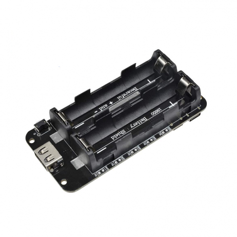
2 x 18650 Lithium Battery Shield for Arduino, ESP32, ESP8266
Provides the high-current 5 V supply needed to reliably power ESP32 and the SIM800L module in GPS tracker builds.
Common Issues and Fixes
GPS has no fix indoors
GPS signals are extremely weak and cannot penetrate concrete buildings. For testing, hold the module near an open window or use a simulated NMEA signal over USB. The NEO-6M has a ceramic patch antenna — it must have a clear view of the sky to lock onto 4+ satellites. In India, GNSS also supports NavIC (IRNSS) satellites which improve fix times in the subcontinent. The NEO-M8N supports NavIC while the older NEO-6M does not.
SIM800L not responding to AT commands
The three most common causes: (1) insufficient power supply — the LED on the module should pulse every 3 seconds during normal network search; (2) baud rate mismatch — try autobaud by sending AT at multiple baud rates; (3) the module is in sleep mode — send a HIGH pulse on the DTR pin or cycle power.
Garbage characters in Serial Monitor
This almost always means a baud rate mismatch between what you set in begin() and what is set in the Serial Monitor dropdown. Both must match exactly. Also ensure the Serial Monitor line ending is set to “Both NL & CR” when sending AT commands to the GSM module.

30Pin ESP32 Expansion Board with Type-C and Micro USB Dual Interface
Breaks out all ESP32 pins cleanly onto screw terminals, making multi-UART wiring for GPS and GSM projects much more manageable.
Frequently Asked Questions
How many UART devices can the ESP32 handle simultaneously?
Three — one per hardware UART (UART0, UART1, UART2). UART0 is typically used by the USB serial programmer for debug output, leaving UART1 and UART2 for peripherals. If you need more than two external serial devices, you can use I2C-to-UART bridge chips like the SC16IS750 to expand to additional virtual COM ports over I2C.
Does the ESP32 support RS-232 or RS-485?
The ESP32 UART logic is 3.3 V TTL. For RS-232 (used in industrial meters and PLCs), you need a MAX232 or MAX3232 level converter chip. For RS-485 (half-duplex differential signalling used in Modbus), use a MAX485 or SP3485 transceiver. The ESP32 ESP-IDF framework has native RS-485 support with automatic driver enable/direction control.
Can I use UART for flashing OTA updates while GPS is running?
OTA over Wi-Fi or BLE does not use UART, so GPS and GSM operations are unaffected. If you are using the UART0 for serial flashing, the serial programmer conflicts with any sketch that also uses UART0 for its own serial communication — use UART2 or UART1 for peripherals so UART0 remains clean for programming.
What baud rate should I use for GPS modules?
Standard GPS modules default to 9600 baud. u-blox modules support up to 460800 baud after configuration via u-center software. Higher baud rates allow faster NMEA sentence delivery but consume more UART RX buffer — 9600 baud at 1 Hz update rate is sufficient for most vehicle tracking applications.
Build Your GPS GSM Tracker with ESP32
Zbotic has all the ESP32 boards, sensors, and accessories you need for serial communication projects. Fast shipping across India.


Add comment