
The voltage divider circuit is one of the most versatile and frequently used building blocks in electronics. It uses two resistors to produce an output voltage that is a fraction of the input — and it shows up everywhere: from battery voltage monitors and sensor signal conditioning to ADC input scaling and biasing circuits.
In this guide, you will learn the voltage divider formula, how to calculate values for any application, and see a range of practical real-world examples with the components you actually use in your projects.
What Is a Voltage Divider?
A voltage divider (also called a potential divider) is a circuit made of two resistors connected in series across a supply voltage. The output is taken from the junction between the two resistors. Because the two resistors share the supply voltage in proportion to their values, you can predict exactly what output voltage you will get at the junction.
The basic circuit looks like this: Vin connects to the top of R1. The bottom of R1 connects to the top of R2 and to the output (Vout). The bottom of R2 connects to GND. Simple, elegant, and powerful.
The Voltage Divider Formula
The output voltage of a voltage divider is calculated with this formula:
Vout = Vin × R2 / (R1 + R2)
Where:
- Vin = Input voltage (supply)
- R1 = Top resistor (connected from Vin to output node)
- R2 = Bottom resistor (connected from output node to GND)
- Vout = Output voltage (at the junction of R1 and R2)
Notice that Vout depends only on the ratio of R2 to the total resistance (R1 + R2). If R2 equals R1 (both same value), Vout = Vin / 2. If R2 is much smaller than R1, Vout approaches 0. If R2 is much larger than R1, Vout approaches Vin.
How It Works: Step by Step
Here is the physics behind the formula. In a series circuit, the same current flows through both resistors. By Ohm’s Law:
Total current: I = Vin / (R1 + R2)
Voltage across R2 (which is Vout): Vout = I × R2 = Vin × R2 / (R1 + R2)
That is the entire derivation. The voltage divides between R1 and R2 in proportion to their resistances. The bigger R2 is relative to R1, the larger the fraction of Vin that appears at Vout.
Example Calculations
Example 1: Basic Voltage Halving
Vin = 10V, R1 = 10kΩ, R2 = 10kΩ
Vout = 10 × 10,000 / (10,000 + 10,000) = 10 × 0.5 = 5V
Equal resistors always give exactly half the input voltage. This is frequently used to create a mid-rail reference point.
Example 2: Reducing 12V to 5V
Vin = 12V, Vout = 5V. What ratio do we need?
Vout / Vin = R2 / (R1 + R2) = 5 / 12 = 0.4167
Choose R2 = 10kΩ. Then: 0.4167 = 10,000 / (R1 + 10,000)
R1 + 10,000 = 10,000 / 0.4167 = 24,000 → R1 = 14kΩ
Use standard values: R1 = 15kΩ and R2 = 10kΩ → Vout = 12 × 10 / 25 = 4.8V (close enough for most applications)
Example 3: Finding Vout from Known Resistors
Vin = 3.3V, R1 = 22kΩ, R2 = 47kΩ
Vout = 3.3 × 47,000 / (22,000 + 47,000) = 3.3 × 47,000 / 69,000 = 3.3 × 0.681 = 2.25V
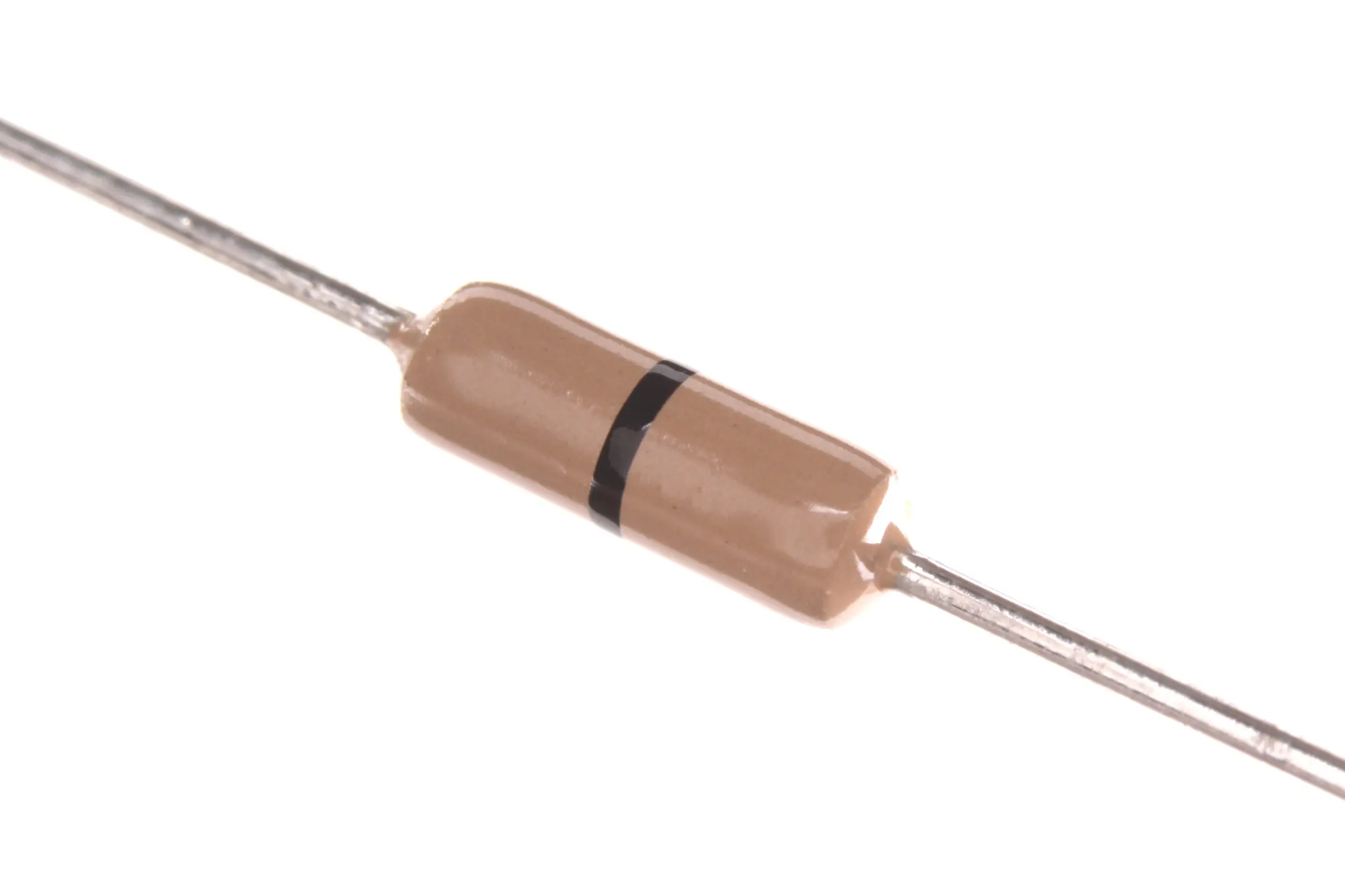
Carbon Film Resistors – Pack of 100
Build voltage dividers and other resistive networks with ease — keep a varied stock of carbon film resistors in your parts drawer for quick prototyping.
Level Shifting: 5V to 3.3V for ESP32/ESP8266
This is one of the most practical voltage divider applications for Indian electronics hobbyists. The ESP32 and ESP8266 are 3.3V logic devices — feeding them a 5V signal from an Arduino or sensor can damage them. A simple resistor voltage divider solves this perfectly for slow signals.
Circuit for 5V → 3.3V level shifting:
- Vin = 5V (from Arduino digital output or sensor)
- Target Vout = 3.3V
- Vout / Vin = 3.3 / 5 = 0.66
- Choose R2 = 22kΩ. Then R1 = R2 × (1/0.66 − 1) = 22,000 × 0.515 ≈ 11.3kΩ
- Use R1 = 10kΩ, R2 = 22kΩ → Vout = 5 × 22 / 32 = 3.44V — acceptable for 3.3V logic
Important caveat: Resistor dividers work for level shifting only for low-frequency, high-impedance inputs. For I2C, SPI, or UART at high speeds, the resistors add capacitance loading and slow the rising edges — use a dedicated level shifter IC for digital protocols above 100kHz.
Battery Voltage Monitor with Arduino
A common project is reading battery voltage with an Arduino’s analog input (which accepts 0–5V max). If you are monitoring a 12V lead-acid battery, you need to scale it down to the ADC range.
Design for 12V → 5V input to Arduino ADC:
- Vin = 12V (max), Vout(max) = 5V
- Ratio = 5/12 = 0.4167
- Use R1 = 15kΩ, R2 = 10kΩ → Vout = 12 × 10/25 = 4.8V ✓
- Total current through divider = 12V / 25kΩ = 0.48mA (negligible drain)
In Arduino code, read the ADC and reverse the calculation: Vbattery = analogRead(A0) × (5.0 / 1023) × (25 / 10). With this, you get an accurate battery voltage reading on a 16×2 LCD display or serial monitor.
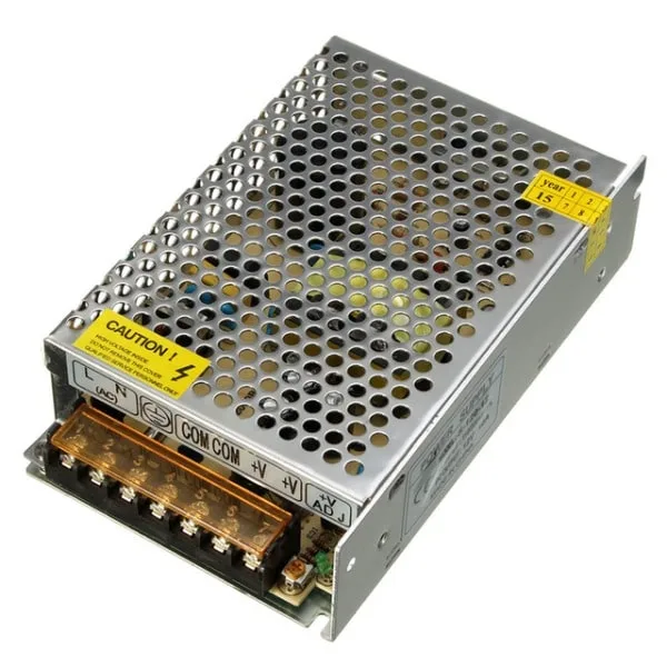
12V 10A SMPS – 120W DC Metal Power Supply
A stable 12V supply is the ideal Vin for voltage divider experiments and real-world power circuits — this quality SMPS delivers clean regulated output.
Sensor Signal Conditioning
Many sensors produce voltages outside the range of a microcontroller’s ADC. The LM35 temperature sensor produces 10mV per °C, so at 100°C it outputs 1.0V — well within ADC range. But some sensors use ratiometric output up to their supply voltage.
A voltage divider can also bias sensors. A classic example is a resistive sensor like an NTC thermistor or LDR (light-dependent resistor). Place the sensor as R1 or R2 in the divider with a fixed resistor as the other half — the output voltage changes as the sensor’s resistance changes with temperature or light. This forms the basis of a simple analog sensor circuit.
Thermistor voltage divider:
- Vin = 5V, Rfixed = 10kΩ (in place of R1), RNTC = variable (in place of R2)
- At 25°C, NTC = 10kΩ → Vout = 5 × 10/20 = 2.5V
- At 50°C, NTC ≈ 4kΩ → Vout = 5 × 4/14 = 1.43V
- Arduino ADC reads Vout → apply the Steinhart-Hart equation to convert to temperature

LM35 Temperature Sensor
A classic analog temperature sensor whose output voltage is linearly proportional to temperature — perfect for ADC-based temperature measurement with an Arduino voltage divider circuit.
Potentiometer as an Adjustable Voltage Divider
A potentiometer is essentially a voltage divider with an adjustable wiper. Connect the two outer terminals to Vin and GND; the middle wiper terminal provides a voltage that varies from 0 to Vin as you turn the knob.
Potentiometers are used for:
- Volume and brightness controls
- Speed control for motors (as an ADC input to a microcontroller)
- Calibration and offset adjustment in sensor circuits
- Setting the threshold voltage on a comparator
The wiper position maps linearly (for linear tapers) or logarithmically (for audio taper pots) to the output voltage, giving you an intuitive analogue input method.
The Loading Effect: Why Output Impedance Matters
This is the most important thing to understand beyond the basic formula: a voltage divider is only accurate when the load connected to Vout draws negligible current compared to the divider current. If a load with low resistance is connected, it effectively adds a third resistor in parallel with R2, changing the divider ratio and lowering Vout below the calculated value.
Rule of thumb: The load impedance should be at least 10 times R2 to keep the error under 10%. For high-impedance loads (like ADC inputs, op-amp inputs, or comparator inputs, which draw microamps), the loading effect is negligible. For low-impedance loads (like motors, LEDs without resistors, or speakers), a voltage divider is not the right solution — use a voltage regulator or op-amp buffer instead.
Example of loading effect:
Divider: R1 = 10kΩ, R2 = 10kΩ, Vin = 10V. Unloaded Vout = 5V.
Now connect a 10kΩ load across Vout. R2 effective = 10kΩ || 10kΩ = 5kΩ.
Vout loaded = 10 × 5/(10+5) = 3.33V — a 33% drop. Significant!
Limitations and When Not to Use a Voltage Divider
A resistor voltage divider is a simple, passive circuit with real limitations:
- Not suitable for powering loads: The output voltage drops under load (loading effect). Use a linear regulator (7805, LM317) or buck converter for regulated power delivery.
- Constant current drain: Even with no load, the divider continuously draws I = Vin / (R1 + R2). For battery-powered applications, use high-value resistors (100kΩ+) to minimise this drain.
- Not for high-frequency signals: Parasitic capacitance creates a low-pass filter effect. For RF or fast digital signals, use a purpose-designed attenuator or level shifter IC.
- Temperature coefficient: Resistors drift with temperature. For precision reference voltages, use a dedicated voltage reference IC rather than a resistor divider.

1.5 Ohm Metal Film Resistors (Pack of 100)
For precision voltage dividers, metal film resistors with 1% tolerance deliver far more accurate output than standard 5% carbon film types — ideal for sensor conditioning and ADC scaling.
Frequently Asked Questions
What is the voltage divider formula?
The voltage divider formula is Vout = Vin × R2 / (R1 + R2), where R1 is the top resistor (between input and output node) and R2 is the bottom resistor (between output node and ground). The output voltage is a fraction of the input, determined by the ratio of R2 to the total series resistance.
Can I use a voltage divider to power a 3.3V component from 5V?
Only for very high-impedance loads like ADC inputs or op-amp inputs. A voltage divider cannot deliver significant current while maintaining the target voltage. If the component draws more than about 1/10th of the divider current, the output voltage will drop below the intended value. For powering components, use a 3.3V linear regulator (like the AMS1117-3.3) or a buck converter module.
How do I choose resistor values for a voltage divider?
First decide the ratio: R2 / (R1 + R2) = Vout / Vin. Choose absolute values that balance two concerns: high enough to limit quiescent current (use 10kΩ–100kΩ range), but low enough to be significantly lower than your load impedance. For ADC inputs (impedance typically >1MΩ), 10kΩ to 47kΩ is a good range. For battery monitoring with long battery life, go up to 100kΩ or higher.
What is the difference between a voltage divider and a voltage regulator?
A voltage divider is a simple passive circuit — its output voltage varies with load current (the loading effect). It wastes power continuously through the resistors and cannot maintain a stable output under varying loads. A voltage regulator is an active circuit that maintains a constant output voltage regardless of load current (within its rating). Use a voltage divider only for high-impedance signal scaling; use a voltage regulator to power loads.
Is a potentiometer the same as a voltage divider?
Yes — a potentiometer is a variable voltage divider. It has a resistive track with a wiper that slides along it. The two ends of the track connect to Vin and GND, and the wiper provides Vout. As the wiper moves, R1 and R2 change proportionally (their sum stays constant), so Vout varies continuously from 0V to Vin. This is exactly the voltage divider formula applied with adjustable resistor values.
Apply the Voltage Divider in Your Next Project
The voltage divider is a small circuit with enormous applications. Whether you are scaling an analog sensor output for an Arduino ADC, monitoring a 12V battery from a 5V microcontroller, or safely interfacing a 5V output to an ESP32 input, the formula is always the same: Vout = Vin × R2 / (R1 + R2). Understand the loading effect and know when to use a voltage regulator instead, and you will use this circuit effectively in nearly every project you build.


Add comment