
When designing a rechargeable lithium-ion battery circuit for your next maker project, two ICs come up more often than any other: the TP4056 vs MCP73831 Li-Ion charging IC comparison is a decision every electronics hobbyist in India eventually faces. Both chips are single-cell 4.2V CC/CV chargers, both cost under ₹15 per piece, and both are readily available from Zbotic and other Indian components suppliers. But the differences between them matter enormously depending on your application. This guide breaks down every important parameter to help you make the right choice.
Table of Contents
- Overview: What These ICs Do
- Pinout and Package Comparison
- Charge Current Configuration
- Protection Features
- Input Voltage Range
- Status Indication and Monitoring
- Thermal Management
- Ready-Made Modules in India
- Which IC Should You Use?
- Practical Design Tips
- Frequently Asked Questions
Overview: What These ICs Do
Both the TP4056 and MCP73831 implement the standard Constant Current / Constant Voltage (CC/CV) charging algorithm for single-cell lithium-ion and lithium-polymer batteries. The algorithm works in two phases:
- Constant Current (CC) phase: The charger supplies a fixed current (set by a resistor) until the battery reaches 4.2V. This phase does the bulk of the charging — typically 0%–80% capacity.
- Constant Voltage (CV) phase: The charger holds 4.2V and allows current to taper down naturally. Charging terminates when current falls to approximately 10% of the programmed charge current. This phase fills the remaining 20%.
Neither chip handles multi-cell series packs or requires an external MOSFET for basic operation — they’re fully integrated linear chargers. This simplicity is exactly why they dominate hobbyist and low-power commercial designs worldwide.
Pinout and Package Comparison
The physical and electrical differences start right at the package level:
| Parameter | TP4056 | MCP73831 |
|---|---|---|
| Package | SOP-8 (8-pin) | SOT-23-5 (5-pin) |
| Pin Count | 8 | 5 |
| PCB Footprint | Larger (easier to hand-solder) | Very compact |
| Key Pins | VCC, GND, BAT, PROG, TEMP, /CE, /STDBY, /CHRG | VDD, GND, VBAT, PROG, STAT |
| Manufacturer | Nanjing Top Power ASIC (China) | Microchip Technology (USA) |
| Datasheet Availability | English datasheet widely available | Full English datasheet (Microchip DS) |
The TP4056’s SOP-8 package is significantly easier to hand-solder on a custom PCB than the MCP73831’s tiny SOT-23-5. However, the MCP73831’s smaller footprint makes it ideal for extremely space-constrained designs like wearables or thin PCBs where the SOP-8 won’t fit.
Charge Current Configuration
Both ICs set the charge current using a single external resistor on the PROG pin. However, the formulas and practical ranges differ:
TP4056 Charge Current Formula
I_charge (mA) = 1,200 / R_PROG (kΩ)
Common values:
- R = 1.2 kΩ → 1,000 mA (1A) — maximum rated
- R = 2 kΩ → 600 mA
- R = 3 kΩ → 400 mA
- R = 10 kΩ → 120 mA
The TP4056 is rated for a maximum charge current of 1,000 mA (1A).
MCP73831 Charge Current Formula
I_charge (mA) = 1,000 / R_PROG (kΩ)
Common values:
- R = 2 kΩ → 500 mA
- R = 3.9 kΩ → 256 mA (good for 250mAh LiPo)
- R = 10 kΩ → 100 mA
- R = 100 kΩ → 10 mA (trickle for very small cells)
The MCP73831 is available in two maximum-current variants: MCP73831T-2ACI/OT (500 mA max) and MCP73831T-4.2ACI/OT (variant differences relate to charging voltage — both are 4.2V termination). The practical maximum is 500 mA.
This is the single most important practical difference: TP4056 supports up to 1A charge current; MCP73831 is limited to 500 mA. For charging 2,000+ mAh batteries at 1C rate, the TP4056 is the natural choice. For small 100–500 mAh LiPo cells common in wearables, the MCP73831 is perfectly matched.
Protection Features
This is where the two chips differ most significantly for practical DIY use:
TP4056: Charging Only (no protection) — but modules have it
The TP4056 chip itself only handles charging. It does not protect against over-discharge (battery draining too low) or reverse polarity. However, the widely available TP4056 module PCBs (the small blue or red boards sold everywhere) include a separate DW01A protection IC plus FS8205A dual-MOSFET for a complete protection solution. This combination provides:
- Overcharge protection (via TP4056 itself — terminates at 4.2V)
- Over-discharge protection (via DW01A — cuts off below ~2.5V)
- Over-current/short-circuit protection (via DW01A + FS8205A)
The bare TP4056 IC alone requires you to add protection externally if needed.
MCP73831: Charging Only (no protection)
The MCP73831 is purely a charging controller — no protection whatsoever is included. You must add an external BMS/protection circuit if your application requires over-discharge protection. This is common in designs where the downstream system already has its own protection (e.g., a microcontroller with low-battery detection that shuts down gracefully).
Bottom line on protection: If you buy ready-made TP4056 modules with DW01A (which are the standard), you get charging + protection in one package. With MCP73831 you need to add a protection IC separately unless your system design handles it another way.
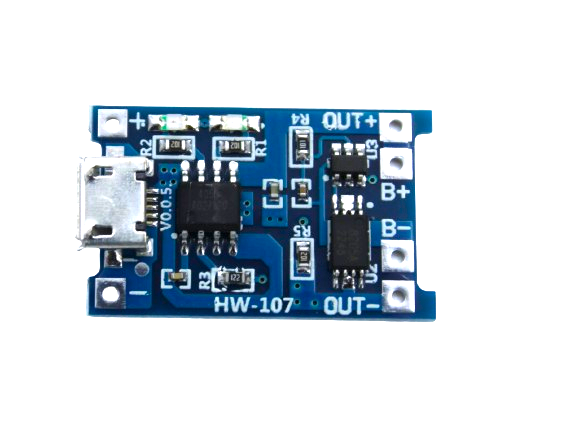
TP4056 1A Li-Ion Battery Charging Board – Micro USB with Current Protection
The complete TP4056 + DW01A module with Micro-USB input. Charges at up to 1A with full overcharge, over-discharge, and short-circuit protection. The go-to charging solution for 18650 and LiPo cells in DIY projects.
Input Voltage Range
Both ICs are linear chargers — the input voltage must be higher than 4.2V (the battery full-charge voltage), and the excess voltage is dissipated as heat:
| Parameter | TP4056 | MCP73831 |
|---|---|---|
| Input Voltage Range | 4.5V – 8V | 3.75V – 6V |
| Typical Input (USB 5V) | Yes (ideal) | Yes (ideal) |
| Works with USB-C 9V/12V? | Yes (up to 8V) | No — max 6V |
| Min Input (no-charge) | ~4.35V | ~4.35V |
The TP4056 has a slightly wider input range, tolerating up to 8V. This means it can be powered directly from a lithium-ion pack being used as input for other purposes, or from a slightly elevated 5V rail. The MCP73831’s 6V maximum is tighter — always verify your input won’t exceed this under load-transient or overvoltage conditions.
Status Indication and Monitoring
Both ICs provide a status output pin, but the TP4056 has an advantage here:
- TP4056: Two open-drain status pins —
/CHRG(low when charging) and/STDBY(low when charge complete). You can connect LEDs directly between VCC and these pins with a resistor. One LED turns on during charging, another when done. Also has a/CE(Charge Enable) pin to enable/disable charging under software control. - MCP73831: Single
STATpin. This tri-state output indicates: charging (low), complete (high-impedance), and shutdown/no battery (high). Requires more careful LED circuit design to distinguish all three states. No dedicated charge-enable pin — input voltage control is used to enable/disable charging.
For Arduino/ESP32 projects where you want to read charging status digitally (e.g., to display battery status on an OLED), the TP4056’s dual output pins make firmware simpler. You can read /CHRG and /STDBY as two digital inputs and distinguish four states (charging, standby, fault/no battery, and pre-charge).
Thermal Management
Both are linear chargers, meaning they convert excess voltage to heat. Power dissipation = (VIN − VBAT) × ICHARGE. At 5V input, 1A charge current, and VBAT = 3.7V:
P_dissipation = (5.0 − 3.7) × 1.0 = 1.3 W
Both ICs include thermal shutdown protection and will automatically reduce charge current if the die temperature exceeds their threshold (~150°C for TP4056, ~150°C for MCP73831). This “thermal fold-back” means the IC self-protects without requiring external heat management for most designs. However, at full 1A charge current, the TP4056 module will get noticeably warm — this is normal but warrants good airflow in an enclosure.
The MCP73831’s SOT-23-5 package has a lower thermal mass and less PCB copper for heatsinking, which is one reason its maximum current is lower — it cannot safely dissipate the heat that a 1A linear charger generates.
Ready-Made Modules in India
For prototyping and small-batch production, ready-made breakout modules are the most practical option:
TP4056 modules are ubiquitous in India. The standard blue/red PCB includes TP4056 + DW01A + FS8205A, a Micro-USB or Mini-USB connector, two status LEDs (red=charging, blue=done), solder pads for BAT+/BAT−, and OUT+/OUT−. These cost ₹15–40 each and are available everywhere from Zbotic to local electronics shops.
MCP73831 modules are less common as pre-made boards in India but can be found on specialty electronics sites. They’re more commonly used in custom PCB designs, particularly in IoT products where their compact footprint justifies the more involved PCB layout.
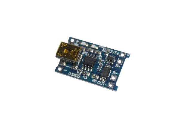
TP4056 1A Li-ion Lithium Battery Charging Module with Current Protection – Mini USB
The classic TP4056 module with Mini-USB connector, DW01A protection IC, and status LEDs. Ideal for projects where you already have Mini-USB cables or connectors. Charges at 1A with full protection.
Which IC Should You Use?
Here’s a practical decision guide based on common Indian maker use cases:
Choose TP4056 when:
- Charging a 1,000–3,000 mAh 18650 cell (need 500mA–1A charge rate)
- Using ready-made modules for prototyping (fastest path to working circuit)
- You want charging + protection in one module without extra components
- Building power banks, flashlights, or battery-backed Arduino projects
- You’re new to battery circuits and want the simplest, safest solution
- Input is a standard 5V USB charger
Choose MCP73831 when:
- Charging a small LiPo (100–500 mAh) in a wearable or IoT device
- Designing a custom PCB where footprint is critical (wristbands, sensor nodes, etc.)
- Your system already has battery protection handled elsewhere (external BMS, downstream MCU)
- You need Microchip’s automotive/industrial-grade supply chain reliability
- The 500 mA max current is sufficient for your battery size
- You’re designing a commercial product and prefer a well-documented US manufacturer
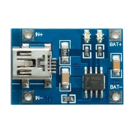
TP4056 1A Li-ion Lithium Battery Charging Module – Mini USB
A clean, no-frills TP4056 charging module at Mini-USB. Perfect for embedding into battery-powered projects where you need a compact, proven charging solution without extra circuitry.
Practical Design Tips
Avoid Charging and Load Simultaneously (Path Sharing)
Both ICs are designed to charge the battery only — they don’t manage a load simultaneously connected to the battery. If your circuit needs to run from battery while charging (“power path” operation), you need an additional load-sharing circuit or a dedicated power path management IC (e.g., BQ24090, MCP73871, or the popular TP5100 which handles up to 2A and includes integrated power path).
Decouple the Input Supply
Add at least a 1µF–10µF ceramic capacitor close to the VCC/VDD pin and a 10µF–100µF electrolytic on the input. USB cables have non-trivial impedance, and transient current spikes during CC/CV transition can cause input voltage dips that confuse the charger.
Adjust Charge Current for Battery Size
Always match the PROG resistor to your battery’s rated 1C current. A 500 mAh cell should charge at ~500 mA; a 100 mAh cell at ~100 mA. Charging at too high a rate (above 1C) causes heat, cell damage, and safety risks.
Check Module Authenticity
Counterfeit TP4056 ICs (or modules using lower-quality Chinese clones) are rampant. A genuine TP4056 module will reach a stable 4.20V charge termination voltage ±1%. Use a multimeter to verify the charge termination voltage on a known-good cell — anything above 4.25V per cell is dangerous.
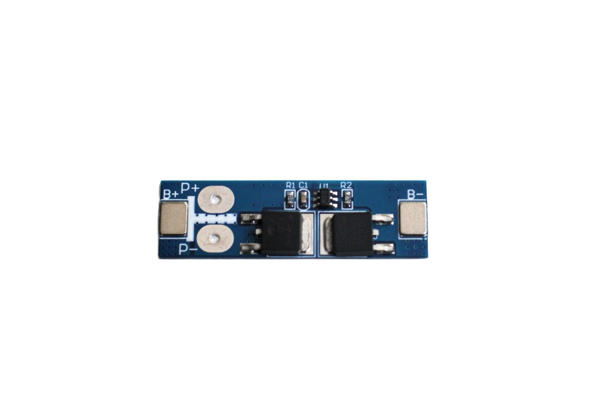
1S 12A 3.6V BMS Battery Protection Board for Li-ion Cell
High-current 12A 1S BMS board — ideal when pairing bare MCP73831 or TP4056 chips with unprotected cells. Handles over-current, over-discharge, and short-circuit independently of the charging IC.
Frequently Asked Questions
Q1: Can TP4056 charge LiPo and Li-ion batteries interchangeably?
Yes. Both standard LiPo and Li-ion cells charge to 4.20V with the same CC/CV algorithm. The TP4056 works for both chemistries. Note that LiHv (high-voltage LiPo) cells charge to 4.35V — do not use a standard TP4056 for these.
Q2: Why does my TP4056 module get hot during charging?
All linear chargers dissipate excess voltage as heat. At 1A charge rate and 5V input with a 3.7V battery, the IC dissipates about 1.3W — enough to feel warm. This is normal. If it’s too hot to touch for more than a second, check that the charge current resistor is correct and the input voltage isn’t above 5.5V.
Q3: Can I use the TP4056 to charge two cells in parallel?
Yes, you can connect two cells in parallel directly and charge them as if they were one larger cell — provided the cells are closely matched in voltage before connecting (within 0.1V of each other). However, the combined capacity will be double, so the 1A charge current equates to only 0.5C — perfectly safe, but slow for large cells.
Q4: What replaces both TP4056 and MCP73831 for higher-current applications?
For single-cell charging above 1A, look at the TP5100 (2A, power path management), IP5108 (for power banks with USB-C PD input), or the CN3791 (for solar-direct charging). For multi-cell packs, dedicated balance charger ICs or dedicated BMS+MPPT combinations are more appropriate.
Q5: Is the TP4056 suitable for solar charging from a small panel?
In theory yes — if your panel output is regulated to 5V. However, solar panel voltage is unregulated and can spike well above 5V in open-circuit conditions. Always use an MPPT charge controller between the panel and battery. The TP4056 is fine as the CC/CV charging stage after regulation, but it should not connect directly to a bare panel.
Get the Right Charging Solution for Your Project
For most Indian hobbyist projects — power banks, sensor nodes, wearables, and Arduino builds — the TP4056 module is the fastest, safest, and most cost-effective starting point. The MCP73831 shines when you’re designing a compact custom PCB and need the precision of a Microchip part with excellent documentation and design support.
Zbotic stocks TP4056 modules in multiple connector variants (Micro-USB, Mini-USB, USB-C) alongside BMS protection boards and 18650 holders to complete your battery circuit. Shop our Batteries, Power & Charging range and build with confidence!


Add comment