
Thermal Resistance in Electronics: Complete Heatsink Selection Guide
Every power transistor, voltage regulator, and motor driver IC generates heat during operation. Without proper thermal management, these components overheat, their performance degrades, and eventually they fail — sometimes spectacularly. Understanding thermal resistance and heatsink selection is a fundamental electronics design skill that separates reliable, long-lived circuits from ones that burn out. This guide explains thermal resistance (θ_JA, θ_JC, θ_CS, θ_SA), how to calculate the required heatsink, and how to pick the right one for your project — whether you’re building a power supply, motor controller, or audio amplifier in India.
The Thermal Circuit Analogy
The most useful way to think about thermal management is as an electrical circuit analogy. Heat flowing from junction to ambient is like current flowing through a series of resistors:
- Heat (power dissipated) is analogous to current (Amperes)
- Temperature difference is analogous to voltage (Volts)
- Thermal resistance (°C/W) is analogous to electrical resistance (Ohms)
Ohm’s Law for thermal circuits: ΔT = P × R_thermal
Where ΔT is the temperature difference across a thermal interface, P is the power dissipated in watts, and R_thermal is thermal resistance in °C/W.
This analogy is powerful because it lets you calculate temperatures at every point in the thermal path — just like calculating voltage drops across series resistors. The total thermal resistance from junction to ambient is the sum of each interface’s resistance:
R_JA_total = R_JC + R_CS + R_SA
Where JC = junction to case, CS = case to heatsink, SA = heatsink to ambient.
Types of Thermal Resistance
θ_JA — Junction to Ambient
This is the total thermal resistance of the component from the silicon die (junction) to the surrounding air (ambient), without any heatsink. It appears on every power device datasheet. A lower θ_JA means the device naturally dissipates heat better.
Example: A TO-220 package transistor might have θ_JA = 50°C/W. Dissipating 2W raises the junction 100°C above ambient. At 40°C ambient (common in India), the junction reaches 140°C — close to the typical 150°C maximum for silicon transistors. Without a heatsink, you’re very close to the limit at only 2W dissipation.
θ_JC — Junction to Case
This is the thermal resistance from the silicon die to the exterior of the package (the metal tab or bottom surface). It’s a fixed property of the package — you can’t change it. For a TO-220 package with direct mounting tab, θ_JC is typically 1–5°C/W. This low value means the case temperature closely follows the junction temperature when the junction power changes.
θ_CS — Case to Heatsink
The interface between the component case and the heatsink. Even though both surfaces look smooth, microscopic irregularities create air pockets that impede heat flow. θ_CS without thermal interface material (TIM) is 0.5–2°C/W. With thermal paste or a pad, it drops to 0.1–0.5°C/W. Electrical isolation requirements (mica, silicone pad) add 0.5–1.5°C/W.
θ_SA — Heatsink to Ambient
This is the thermal resistance of the heatsink itself — its ability to transfer heat to the surrounding air. It’s the number printed on every heatsink datasheet (e.g., “12°C/W” or “3°C/W”). A lower θ_SA means a more effective heatsink. You choose this value by selecting the right heatsink.
Heatsink Thermal Resistance Calculation
Here’s the complete calculation procedure for selecting a heatsink:
Step 1: Determine Power Dissipation
Calculate or measure how much power your device dissipates. For a linear voltage regulator (like LM7805) dropping 12V to 5V at 1A:
P = (V_in – V_out) × I = (12 – 5) × 1 = 7W
Step 2: Find Maximum Junction Temperature
From the datasheet, find T_j(max). For most silicon power devices, this is 125°C or 150°C. Use 125°C for conservative design.
Step 3: Set Ambient Temperature
For India, use 45–50°C ambient to account for summer conditions and enclosure heat buildup. This is more conservative than the 25°C assumed in most Western designs.
Step 4: Calculate Required Total Thermal Resistance
R_total = (T_j(max) – T_ambient) / P = (125 – 50) / 7 = 10.7°C/W
Step 5: Subtract Known Thermal Resistances
From the datasheet, θ_JC for LM7805 TO-220 = 5°C/W. Add θ_CS with thermal paste = 0.5°C/W.
R_SA(required) = R_total – R_JC – R_CS = 10.7 – 5 – 0.5 = 5.2°C/W
You need a heatsink with θ_SA ≤ 5.2°C/W. Pick the next smaller standard heatsink — for example, a heatsink rated at 4°C/W gives comfortable margin.

LM35 Temperature Sensor
Monitor heatsink or component temperatures in real-time with the LM35 — outputs 10mV/°C, directly readable by any ADC. An essential tool for validating your thermal design and detecting overheating in your builds.
Worked Example: Motor Driver
You’re running an L298N motor driver at 12V, 2A per channel (4A total). The L298N has a typical saturation voltage of 3V at 2A. Power dissipation per channel:
P = V_sat × I = 3 × 2 = 6W per channel = 12W total
With θ_JC = 3°C/W, θ_CS = 0.5°C/W, and India ambient 45°C:
R_SA(required) = (125 – 45)/12 – 3 – 0.5 = 6.67 – 3 – 0.5 = 3.17°C/W
You need a heatsink of 3°C/W or better for an L298N running at full load in Indian conditions. The standard small heatsink included with many L298N modules is around 10–15°C/W — far too small for sustained full-load operation.
Thermal Interface Materials (TIM)
The gap between a component’s metal tab and the heatsink surface is filled with thermal interface material to minimise contact resistance. Several options:
| TIM Type | θ_CS (approx) | Insulating? | Notes |
|---|---|---|---|
| No TIM (dry) | 1–3°C/W | — | Worst case, air pockets |
| Thermal paste / grease | 0.1–0.5°C/W | No | Best thermal performance, needs isolation if required |
| Mica washer | 0.5–1.5°C/W | Yes (2–3kV) | Use with thermal paste on each face |
| Silicone thermal pad | 0.5–2°C/W | Yes | Convenient, reusable, slightly worse than mica+paste |
| Bergquist/Fujipoly advanced pad | 0.1–0.3°C/W | Yes | High-performance, costly, used in production electronics |
For Indian hobbyist projects, use white thermal paste (available at computer accessory shops) with a mica washer when isolation is required. This gives θ_CS of about 0.5–0.8°C/W — acceptable for most designs. Always torque the mounting screw uniformly and not too tight (cracking TO-220 packages).
Types of Heatsinks and When to Use Them
TO-92 / SOT-23 Clip Heatsinks
Tiny clip-on heatsinks for small packages. Reduce θ from ~200°C/W (still air, no heatsink) to about 50–100°C/W. Suitable for small regulators dissipating <0.5W. Very common in Indian electronics shops — usually a small finned aluminium clip.
TO-220 Heatsinks (Most Common)
The workhorses for hobbyist power electronics. Available in sizes from “barely useful” (20°C/W, tiny) to “large finned” (3°C/W). The TO-220 package — used by 7805, IRF540N, L7812, and hundreds of other common devices — has a standardised mounting hole. Most TO-220 heatsinks cost ₹20–80 at Indian electronics shops.
Extruded Aluminium Profiles
Larger projects (amplifiers, VFDs, high-power motor drivers) use extruded aluminium heatsink profiles. These are sold by length in India from ₹100–500 depending on size. Cut to length with a hacksaw. Drill and tap mounting holes as needed. Thermal resistance scales inversely with fin area — longer profiles = lower resistance.
PCB-Mount Heatsinks
For SMD power packages (D2PAK, DPAK), there are small SMD heatsinks that solder directly to the PCB. More common in production electronics. For hobbyists, a PCB copper pour (exposed copper area connected to the component’s thermal pad) is often more practical.
Custom DIY Heatsinks
An aluminium block, a CPU cooler from an old PC, or even a thick piece of copper pipe can work as a heatsink for non-critical applications. The key is large surface area. Rule of thumb: a flat aluminium plate dissipates about 8–10 mW per cm² in still air. A 10×10 cm (100 cm²) plate can handle about 1W without significant temperature rise above ambient.
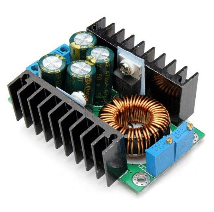
300W 10A DC-DC Step-down Buck Converter Module
This 300W module dissipates significant heat at high loads. Notice the large heatsink on the main switching transistor — a practical example of heatsink sizing for a 10A power design. Calculate θ_SA requirements before mounting in an enclosure.
Passive vs Active (Fan) Cooling
Passive cooling (natural convection from a heatsink alone) works well up to moderate power levels. Once your required heatsink becomes unwieldy, or if the design must fit in a compact enclosure, active cooling with a fan is necessary.
When to Use a Fan
- Power dissipation >20W in a compact enclosure
- Required heatsink would be too large for the available space
- Temperature-sensitive components nearby (electrolytic capacitors, op-amps)
- Intermittent high-load applications where passive can’t shed heat fast enough
How Much Does a Fan Help?
Forced air cooling from a fan can reduce heatsink thermal resistance by 2–5× compared to natural convection, depending on airflow velocity. A heatsink rated at 10°C/W in still air might be 2–4°C/W with a 5 m/s airflow (achievable with a small 80mm PC case fan). This lets you use a much smaller heatsink for the same cooling power.
Fan Placement
Place the fan so air flows across the heatsink fins — not perpendicular to them. Fin orientation in extruded heatsinks is designed for vertical natural convection; rotate the heatsink 90° for horizontal forced airflow for best performance. Ensure there’s an exhaust path for heated air out of the enclosure.
Designing for India’s Hot Climate
Indian electronics designers face thermal challenges that engineers in cooler climates don’t worry about as much:
Higher Ambient Temperature
With ambient temperatures commonly reaching 40–50°C in summer across much of India, the thermal budget is tighter. A component with a 125°C junction limit and 50°C ambient has only 75°C of headroom. The same component in a European 20°C ambient has 105°C of headroom — 40% more. Always design for worst-case Indian summer ambient, not lab-air-conditioned 25°C.
Enclosure Considerations
Sealed enclosures trap heat. A component dissipating 5W in a sealed plastic box raises internal ambient temperature significantly above external ambient. Add 15–25°C to your ambient temperature estimate when calculating heatsink requirements for enclosed equipment.
Electrolytic Capacitor Derating
Electrolytic capacitors are highly temperature-sensitive. Their rated life (usually 2000h at 105°C) roughly doubles for every 10°C of temperature reduction. An electrolytic cap running at 85°C in India has about 500% longer life than one running at 105°C. Keep electrolytics away from hot power devices, or add heatsinking specifically to reduce the local temperature around capacitors.
Derating Power Devices
Standard practice in Indian industrial electronics is to derate power devices to 50–70% of their rated maximum. If a transistor is rated for 10A at 25°C, design to operate it at 5–7A at 45°C Indian ambient. This conservative approach significantly extends device life in harsh Indian conditions.
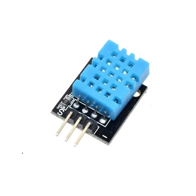
DHT11 Digital Temperature and Humidity Sensor Module
Monitor ambient temperature and humidity inside enclosures to validate your thermal design. Pair with an Arduino or ESP8266 to log temperature data and confirm your heatsink is keeping components within safe limits.
Component and Tool Recommendations
For thermal monitoring and power circuit building, the right sensors and modules make validation much easier:

DHT11 Temperature And Humidity Sensor Module with LED
This module version adds a power LED indicator for easy field verification. Ideal for building simple thermal monitoring circuits to validate heatsink performance in real-world Indian ambient conditions.

12V 10A SMPS 120W DC Metal Power Supply
A robust 120W SMPS with metal enclosure for improved heat dissipation. The metal casing acts as a large heatsink — a good example of enclosure-as-heatsink design. Perfect for powering motor drivers and power electronics projects.
Frequently Asked Questions
Q: How do I know if my component needs a heatsink?
Calculate: P × θ_JA + T_ambient. If this exceeds 0.8 × T_j(max), you need a heatsink. For example, an LM7805 dissipating 3W with θ_JA = 50°C/W gives 3 × 50 = 150°C junction rise, which added to 40°C ambient = 190°C — well above the 125°C max. A heatsink is essential. Quick rule: if a component gets too hot to touch (>60°C) during normal operation, it needs a heatsink.
Q: Can I use two smaller heatsinks in parallel on one device?
Only if both heatsinks can be mechanically attached to the same device. Some TO-3 packages allow dual heatsink mounting. More practically, if space allows, a single larger heatsink is always simpler. The combined thermal resistance of two parallel heatsinks is half of each individual one — the same as parallel electrical resistors.
Q: Does the heatsink orientation matter for passive cooling?
Yes, significantly. Heatsink fins should be oriented vertically for best natural convection — hot air rises, pulling cooler air in from below. Horizontal fins trap hot air between fins and reduce convection. Mounting a heatsink with fins horizontal can increase effective θ_SA by 20–40%.
Q: What is the purpose of thermal compound on a CPU heatsink — same principle?
Exactly the same principle. CPU thermal paste fills microscopic gaps between the CPU heat spreader and the cooler base, reducing θ_CS from 2–3°C/W (dry) to 0.1–0.3°C/W (with quality thermal compound). The electronics thermal resistance model is identical to PC cooling — both are applications of the same thermal circuit theory.
Q: Can I use a Peltier (TEC) cooler instead of a heatsink?
Peltier coolers (thermoelectric coolers) actively pump heat from cold to hot side. They can cool a component below ambient temperature. However, they consume power themselves (often more than they remove) and still need a large heatsink on their hot side. They’re used for IR cameras, laser diodes, and precision temperature control — not for general power electronics where a heatsink is far more efficient.
Build Thermally Reliable Electronics with Zbotic
From temperature sensors for real-time monitoring to high-quality power supply modules, Zbotic has the components and tools you need to build electronics that survive India’s climate reliably. Explore our full range and get fast delivery across India.


Add comment