
Voltage Reference IC: LM4040, REF02 Precision Applications
A voltage reference IC like the LM4040 is the foundation of every precision analog circuit. Whether you’re calibrating a multimeter, building a 16-bit DAC output stage, designing an accurate battery fuel gauge, or creating a precision ADC reference for a data acquisition system, the quality of your voltage reference directly determines your circuit’s accuracy. In this guide, we explore the LM4040 shunt reference, the REF02 series reference, and how to choose and apply voltage reference ICs in Indian maker and industrial projects.
What Is a Voltage Reference IC?
A voltage reference IC produces a stable, accurate output voltage that changes minimally with temperature, supply voltage variations, load current, and time. Unlike a simple Zener diode (which has poor temperature stability and high dynamic impedance) or a regulated power supply (which is optimized for current delivery rather than voltage accuracy), a precision voltage reference IC is specifically engineered to maintain its output voltage to within a few millivolts over all operating conditions.
Voltage references are used as:
- ADC references: The reference voltage defines the full-scale input range. A 12-bit ADC with 5V reference has 5V/4096 = 1.22mV resolution. If the reference drifts by 5mV, the ADC reading gains a 0.1% offset error — important for precision measurement
- DAC references: Sets the full-scale output voltage. For a 16-bit DAC, a 1ppm/°C reference maintains output accuracy within 65µV/°C — whereas a 5V regulator with 0.1% load regulation could introduce 5mV errors
- Precision comparator thresholds: Fixed reference for window comparators in battery management, overvoltage protection, and level detection circuits
- Calibration standards: Laboratory references with initial accuracy better than 0.05% for calibrating instruments
Shunt Reference vs Series Reference: Key Differences
Shunt Voltage References
A shunt voltage reference (like the TL431, LM4040, or LT1009) is a two-terminal device connected in parallel (shunt) with the load. It draws current to maintain its terminal voltage at the reference value. An external series resistor limits the current. Key characteristics:
- Requires external resistor RS to supply operating current
- Operating current range defines its accuracy window (e.g., 60µA to 15mA for LM4040)
- Works with varying supply voltages as long as minimum current is maintained
- Simple 2-terminal connection (cathode and anode)
- Best for fixed supply voltage applications
Series Voltage References
A series voltage reference (like the REF02, REF3025, LT1236, or MAX6126) is a 3-terminal device in series with the load’s reference input. It regulates its output voltage like an LDO regulator, but optimized for accuracy rather than output current capability. Characteristics:
- Output directly drives the load without external series resistor
- Lower output impedance (typically 0.5–5Ω vs 100Ω+ for shunt)
- Better suited for driving capacitive loads (DAC reference pins)
- Can source and sink current (bidirectional load current)
- Typically more expensive than shunt references

1.5 Ohm 1/4W Metal Film Resistor MFR (Pack of 100)
Precision metal film resistors for voltage reference current-setting and output filtering networks. 1% tolerance essential for accurate reference circuit design. Pack of 100.
LM4040 Shunt Voltage Reference: Complete Guide
The LM4040 from Texas Instruments (originally National Semiconductor) is a micropower precision shunt voltage reference available in fixed output voltages of 2.048V, 2.5V, 3.0V, 4.096V, and 5.0V. It is one of the most widely used references in Indian electronics projects due to its low cost (₹25–60 per IC), small SOT-23 package, and excellent performance.
LM4040 Key Specifications
- Initial accuracy grades: A (0.1%), B (0.2%), C (0.5%), D (1.0%) — choose based on required accuracy
- Temperature coefficient: 50ppm/°C (C grade), 100ppm/°C (D grade)
- Operating current range: 60µA to 15mA
- Output voltage change vs current: Typically 3mV over the full 60µA–15mA range (dynamic impedance ~0.2Ω)
- Reverse current: Up to 20mA (for use as a Zener diode in reverse polarity protection)
- Packages: SOT-23-3 (surface mount), TO-92 (through-hole)
LM4040 Circuit Design — Calculating RS
The series resistor RS sets the operating current of the LM4040:
Itotal = (Vsupply – Vref) / RS
Iref = Itotal – Iload
For stable operation: Iref must stay between Imin (60µA) and Imax (15mA)
Example: LM4040-2.5V as ADC reference with 5V supply, ADC reference current 100µA max:
Choose Iref = 1mA (operating current when Iload = 0)
RS = (5V – 2.5V) / (1mA + 0.1mA) = 2.5V / 1.1mA = 2.27kΩ → use 2.2kΩ standard value
Minimum Iref (at max load): (5V – 2.5V) / 2.2kΩ – 0.1mA = 1.136mA – 0.1mA = 1.036mA ✓ (>60µA)
LM4040 Temperature Performance
The LM4040-A grade (0.1% initial accuracy, 50ppm/°C) over India’s industrial temperature range of 0–70°C produces a maximum drift of:
ΔV = 2.5V × 50ppm/°C × 70°C = 2.5V × 3500ppm = 8.75mV
For a 12-bit ADC with 2.5V reference, 1 LSB = 2.5V/4096 = 0.61mV. An 8.75mV drift equals 14 LSB — significant for precision measurements. For better temperature performance, use the LM4040-A or upgrade to an LT1009 (10ppm/°C, ±0.05% initial accuracy).

0.1/100nF Multilayer Ceramic Capacitor (Pack of 50)
Decoupling and output filter capacitors for voltage reference ICs. Reduces noise and improves transient stability. Essential for precision reference circuit design.
REF02: 5V Precision Series Voltage Reference
The REF02 is a classic 5V precision series voltage reference first introduced by Analog Devices (now also manufactured by Texas Instruments as REF02CP). It is the industry reference (pun intended) for 5V precision applications and has been in production since the 1980s — testament to its robust design.
REF02 Key Features
- Output voltage: 5.0V (±10mV for standard grade, ±2.5mV for E grade)
- Temperature coefficient: 8.5ppm/°C typical (15ppm/°C max for E grade)
- Output current: 10mA source, 1mA sink
- Input voltage range: +7V to +40V (wide supply range)
- Supply current: 1.5mA typical
- Long-term stability: 50ppm/1000 hours (low aging)
- Package: DIP-8, SOIC-8, TO-99 (metal can for best thermal performance)
REF02 Circuit Application
The REF02’s wide input voltage range (7–40V) makes it exceptional for industrial applications powered from 12V or 24V supplies. A single REF02 provides a stable 5V reference for multiple ADCs, DACs, and analog subsystems simultaneously, sourcing up to 10mA — enough for most analog front-end circuits.
For improved noise performance, add a 1µF tantalum capacitor and 100nF ceramic capacitor in parallel at the REF02 output. This reduces noise spectral density from the typical 7µVp-p (0.1Hz–10Hz) to under 3µVp-p — critical for 16-bit and 24-bit ADC applications.
REF02 Adjustable Output
The REF02’s TRIM pin allows fine-tuning of the output voltage by ±5% using a 20kΩ potentiometer from TRIM to ground. This enables factory calibration of the reference to exactly 5.000V, compensating for the initial accuracy error of the specific unit. For volume production, this eliminates the need to select high-precision E grades, reducing BOM cost.
Key Specifications: What the Datasheet Numbers Mean
Initial Accuracy
Expressed as a percentage or absolute voltage error at room temperature (25°C) and specified operating current. For a 2.5V reference with 0.1% accuracy: output voltage = 2.5V ± 2.5mV = 2.4975V to 2.5025V. Higher-accuracy grades cost more but reduce calibration overhead.
Temperature Coefficient (Tempco)
Expressed in ppm/°C. The total voltage change over temperature:
ΔV = Vnom × Tempco (ppm/°C) × ΔT (°C) / 1,000,000
A 5V reference with 25ppm/°C over 0–70°C: ΔV = 5V × 25 × 70 / 1,000,000 = 8.75mV maximum drift.
For a 12-bit ADC: acceptable. For a 24-bit ADC (1 LSB = 0.3µV): catastrophic — you’d need 0.1ppm/°C references that cost ₹2,000–5,000 per IC.
Long-Term Stability (Aging)
Expressed in ppm/1000 hours. A 50ppm/1000h reference used in a 24/7 industrial system will drift 50ppm in the first 1000 hours, then typically much less (aging follows a square-root-of-time law). This is why precision instruments require periodic recalibration.
Load Regulation
Change in output voltage per milliamp of load current change. For a shunt reference, the dynamic impedance (Zref) characterises this. For LM4040: Zref = 0.2Ω typical — a 1mA load change causes only 0.2mV output change.
Line Regulation
Change in output voltage per volt of supply voltage change. Low line regulation is critical when the supply voltage varies (e.g., battery-powered applications). The LM4040 achieves 300µV/V typical — a 1V supply variation causes only 0.3mV output change.
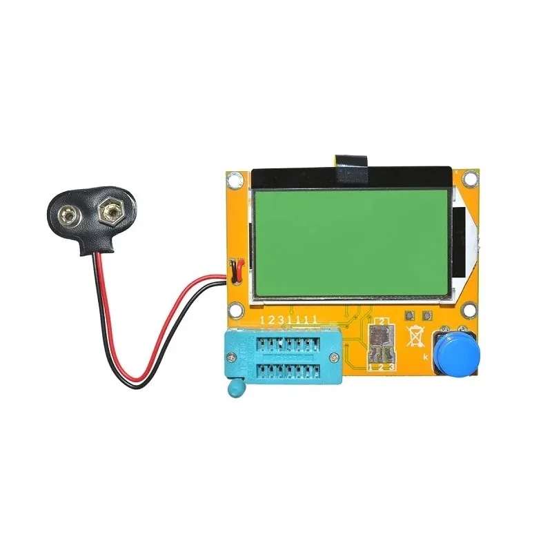
LCR-T4 LCD Graphical Component Tester
Test and verify resistor, capacitor, and transistor values for your voltage reference circuits before assembly. Identifies components automatically with high accuracy.
Using a Voltage Reference with ADCs and DACs
Arduino ADC Reference (External AREF)
The Arduino Uno’s ATmega328P internal 1.1V reference has ±10% accuracy — useless for precision measurements. Using the LM4040-2.5V as an external reference dramatically improves ADC accuracy:
- Connect LM4040-2.5V output to Arduino AREF pin
- Connect 100nF capacitor from AREF to GND (required by Atmel for stability)
- In code:
analogReference(EXTERNAL); - Result: Full-scale = 2.5V, resolution = 2.5V/1024 = 2.44mV/LSB (10-bit ADC)
- With LM4040-A grade (0.1% accuracy): ADC full-scale error = ±2.5mV vs ±110mV with internal reference
Warning: Never apply voltage >5V or <0V to the AREF pin. The AREF pin has weak ESD protection only. Always power the LM4040 from the Arduino's 5V supply, not the Vin rail, to avoid potential overvoltage.
STM32 ADC with External Reference
STM32 microcontrollers have a dedicated VREF+ pin on VQFN and LQFP-100+ packages. For LQFP-64 and smaller, VREF+ is internally connected to VDDA. An external precision reference is most impactful on STM32 devices with the VREF+ pin — the STM32H7 family supports external references up to 3.3V with the 16-bit ADC achieving true 16-bit accuracy with a stable reference.
16-bit DAC Application
For a 16-bit DAC like the DAC8830 (serial interface, 16-bit, 0–VREF output):
- Use REF02 (5V, 8.5ppm/°C) as reference
- 1 LSB = 5V / 65536 = 76.3µV
- Reference tempco contribution over 25°C: 5V × 8.5ppm × 25 = 1.06mV = 14 LSB
- For better accuracy: use LT1236-5 (3ppm/°C) = 0.375mV = 5 LSB over 25°C — expensive but necessary for metrology-grade instruments
Low-Power and Battery-Operated Reference Circuits
For battery-operated IoT sensors and portable instruments, the voltage reference must consume minimal quiescent current. Standard references like the REF02 draw 1.5mA constantly — draining a 2500mAh battery in just 69 days, unacceptable for devices intended to run for months or years on a single charge.
Micropower Options
- LM4040: 60µA minimum operating current — 3× to 25× less than REF02
- MAX6100: 16µA supply current, SOT-23, 2.5V/4.096V, 75ppm/°C
- ISL21090: 4µA supply current, 50ppm/°C, suitable for coin-cell designs
- REF3325: 40µA quiescent, 2.5V, ±0.2% initial accuracy, SOT-23
Duty-Cycled Reference for Ultra-Low Power
For ADC sampling once per minute (temperature logging), the reference can be powered off between samples:
- Connect reference supply through a GPIO pin (via P-channel MOSFET or load switch IC)
- Power on reference 10ms before ADC conversion (allows settling time)
- Take conversion, then power off reference
- Average reference current = 1.5mA × 10ms / 60s = 250nA — 6000× lower than always-on
This technique works for series references (REF02) which settle quickly. Shunt references like LM4040 require their quiescent current to be maintained whenever the reference is needed.
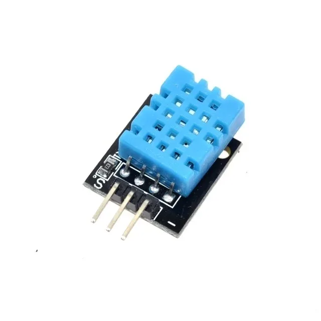
DHT11 Digital Temperature and Humidity Sensor Module
Digital temperature and humidity sensor — uses internal ADC with voltage reference for calibrated readings. Build reference circuits to improve analog sensor accuracy.
Frequently Asked Questions
Can I use a Zener diode instead of a voltage reference IC?
A standard Zener diode has 0.05%/°C temperature coefficient (500ppm/°C) — roughly 10× worse than even a cheap D-grade LM4040. Combined with its high dynamic impedance (20–100Ω vs 0.2Ω for LM4040), a Zener reference introduces significant errors in precision circuits. Use a dedicated reference IC for any application requiring better than 1% accuracy. Zener diodes are only appropriate for non-precision over-voltage clamping or rough regulation.
What voltage reference should I use with an Arduino for precision temperature measurement?
The LM4040-2.5V (C grade, 0.5%, 100ppm/°C) costs around ₹30 and dramatically improves Arduino ADC accuracy compared to the internal 1.1V reference. For the LM35 temperature sensor (10mV/°C), use a gain amplifier to scale up the signal before the ADC, and use the LM4040-2.5V as AREF. For best accuracy with minimum component count, the ADS1115 external 16-bit I2C ADC module includes its own internal reference and provides far better results than the Arduino’s 10-bit ADC.
Why is my LM4040 reference voltage lower than specified?
The most common cause is insufficient operating current. The LM4040 requires a minimum of 60µA to operate in its accurate region. If your series resistor RS is too large, or your load draws too much current, the reference current falls below 60µA and the voltage drops. Calculate Iref = (Vsupply – Vref) / RS – Iload and ensure it exceeds 100µA for a margin.
What is the difference between LM4040 and TL431?
Both are shunt voltage references, but the TL431 is adjustable (2.5V to 36V) while the LM4040 has fixed output voltages. The LM4040 offers better initial accuracy (0.1% vs 0.4% for standard TL431) and better temperature coefficient (50ppm/°C vs 100ppm/°C for TL431). The TL431 costs ₹5–10 and is ideal for SMPS feedback and non-precision applications. The LM4040 at ₹30–60 is for precision measurement applications where accuracy matters.
Can I connect two voltage references in parallel for more current?
For series references (REF02 type): No — two references with slightly different output voltages will fight each other, with the higher voltage reference trying to push current into the lower voltage one, potentially damaging both. Add a small series resistance (10–50Ω) on each output before paralleling. For shunt references (LM4040 type): Yes, they can be paralleled since each device self-limits its current. However, gain is typically not worth it vs simply using a series reference with higher output current rating.
Build precision analog circuits with confidence! Zbotic stocks quality passive components, prototype boards, and measurement tools that Indian electronics engineers and hobbyists need for accurate sensor interfacing and data acquisition designs. Explore our Electronics Components range — with same-day dispatch on in-stock items across India.


Add comment