
Force measurement is at the heart of countless engineering applications — from precision weighing scales and industrial load monitoring to robotics and structural health monitoring. The strain gauge, combined with a Wheatstone bridge circuit, is the gold standard technology that makes all of this possible. Understanding strain gauge theory helps you build accurate, reliable force sensors for your own projects.
In this comprehensive guide, you will learn how strain gauges work at a fundamental level, why the Wheatstone bridge is the ideal interface circuit, and how to wire up a load cell to an Arduino or ESP32 for real-world measurements.
What Is a Strain Gauge?
A strain gauge is a resistive sensor that changes its electrical resistance when it is mechanically deformed (stretched or compressed). The fundamental principle behind this is the piezoresistive effect — the property of certain materials to change their resistivity when mechanical stress is applied.
A typical foil strain gauge consists of a thin metallic foil (usually a nickel-copper alloy called constantan) arranged in a zigzag pattern on a flexible polyimide backing. When the gauge is bonded to a structural element and that element bends or stretches, the foil deforms along with it, causing its resistance to change.
The change in resistance is extremely small — often just a few milliohms for full-scale deflection. This is why the Wheatstone bridge and a precision amplifier are essential companions to the strain gauge.
Key Physical Properties
- Nominal resistance: Most gauges are 120 Ω or 350 Ω (350 Ω gauges have lower self-heating and lower current draw).
- Grid material: Constantan (Cu-Ni) is most common; Karma (Ni-Cr) offers better stability at high temperatures.
- Backing: Polyimide (PI) for general use, glass-fiber for high temperatures.
- Gauge length: Ranges from 0.2 mm (residual stress measurements) to 100 mm (concrete structures).
Gauge Factor and Sensitivity
The gauge factor (GF) is the most critical specification of a strain gauge. It defines how much the resistance changes per unit of applied strain:
GF = (ΔR / R) / ε

Where:
  ΔR = change in resistance (Ω)
  R   = nominal resistance (Ω)
  ε   = mechanical strain (dimensionless, m/m)
For metallic foil gauges, GF ≈ 2.0 to 2.2. Semiconductor strain gauges can have GF of 100–150 but are more temperature-sensitive and non-linear.
Example calculation: A 120 Ω gauge with GF = 2.0 subjected to 1000 microstrain (1000 × 10⁻⁶ m/m) will change resistance by:
ΔR = GF × ε × R = 2.0 × 0.001 × 120 = 0.24 Ω
A 0.24 Ω change in 120 Ω is just 0.2% — clearly too small to measure with a simple voltage divider. This is where the Wheatstone bridge becomes indispensable.
The Wheatstone Bridge Circuit
The Wheatstone bridge was invented by Samuel Hunter Christie in 1833 and popularised by Sir Charles Wheatstone. Its genius lies in measuring small resistance changes with very high accuracy by comparing an unknown resistance against known references.
The bridge consists of four resistors (R1, R2, R3, R4) arranged in a diamond topology with an excitation voltage (Vex) applied across two opposite nodes, and the output voltage (Vout) measured across the other two nodes.
         Vex
          |
     R1 ──┼── R2
     |         |
  Vout+      Vout-
     |         |
     R3 ──┼── R4
          |
         GND
Bridge Balance Equation
When the bridge is balanced (Vout = 0), the following relationship holds:
R1 / R2 = R3 / R4
When a strain gauge replaces one arm (say R1 = R + ΔR), the bridge becomes unbalanced and produces an output voltage:
Vout = Vex × (ΔR / 4R)   [for small ΔR]

Or more precisely:
Vout = Vex × [(R1/(R1+R3)) - (R2/(R2+R4))]
This output voltage is proportional to the applied strain and hence the applied force. The elegance of the bridge is that it inherently cancels out common-mode errors like supply voltage fluctuations and temperature drift (when the same temperature affects all four arms equally).
Bridge Configurations: Quarter, Half, Full
Quarter Bridge
Only one strain gauge is active; the other three arms are fixed precision resistors. This is the simplest configuration.
- Sensitivity: 1× (baseline)
- Temperature compensation: Poor (only one active gauge)
- Use case: Uniaxial stress measurement, educational projects
Half Bridge
Two active strain gauges are used — typically one in tension and one in compression (bending beam). The remaining two arms are fixed resistors.
- Sensitivity: 2× the quarter bridge
- Temperature compensation: Good (both active gauges drift together, cancelling out)
- Use case: Beam bending, torque measurement
Full Bridge
All four arms are active strain gauges. In a bending beam load cell, two gauges are on the tensile face and two on the compressive face.
- Sensitivity: 4× the quarter bridge
- Temperature compensation: Excellent
- Use case: Commercial load cells, precision weighing, high-accuracy force measurement
Commercial load cells (like the ones available at Zbotic) use the full Wheatstone bridge configuration, which is why they are highly accurate and temperature-stable straight out of the box.
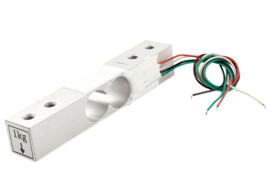
1Kg Load Cell – Electronic Weighing Scale Sensor
Full Wheatstone bridge load cell for precision 0–1 kg force measurement. Compatible with HX711 module and Arduino/ESP32.
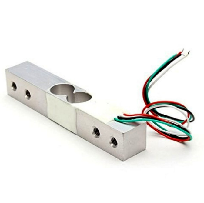
10Kg Load Cell – Electronic Weighing Scale Sensor
Heavy-duty full-bridge load cell rated to 10 kg. Ideal for kitchen scales, industrial weighing, and robotics grippers.
Inside a Load Cell
A load cell is a transducer that converts mechanical force into an electrical signal. Virtually all modern load cells use four strain gauges arranged in a full Wheatstone bridge configuration, bonded to a precision-machined metal body (the spring element).
Typical Load Cell Wire Colors
| Wire Color | Function |
|---|---|
| Red | Excitation + (E+) |
| Black | Excitation − (E−) |
| Green | Signal + (S+) |
| White | Signal − (S−) |
Some load cells have a 6-wire configuration with additional sense wires (SEN+ and SEN−) that allow the amplifier to compensate for voltage drop in long excitation cables — important in industrial settings but not needed for hobby projects.
Load Cell Output
A typical load cell outputs 1–3 mV per volt of excitation (specified as mV/V). A 2 mV/V load cell powered by 5 V will produce a maximum output of just 10 mV at full scale. This tiny signal must be amplified — typically by a factor of 128 or more — before an ADC can read it accurately.
HX711 Amplifier Module
The HX711 is a purpose-built 24-bit analog-to-digital converter and programmable gain amplifier (PGA) designed specifically for Wheatstone bridge sensors. It is the de facto standard for hobbyist and educational load cell projects.
HX711 Key Specifications
- 24-bit ADC resolution
- Selectable gain: 128× or 64× on Channel A, 32× on Channel B
- Internal voltage reference
- On-chip oscillator (no external clock needed)
- 10 Hz or 80 Hz output data rate (selectable via RATE pin)
- Operating voltage: 2.6–5.5 V
- 2-wire serial interface (CLK + DOUT) — compatible with any microcontroller GPIO
Why 24-bit Matters
A 10-bit ADC (like Arduino’s built-in) gives 1024 counts. A 24-bit ADC gives 16,777,216 counts. Even accounting for noise and non-linearity, the HX711 typically delivers 16–18 bits of effective resolution — enough to measure forces with 0.01% full-scale accuracy.
Arduino Wiring and Code
Hardware Connections
| HX711 Pin | Arduino Pin |
|---|---|
| VCC | 5V |
| GND | GND |
| DT (DOUT) | D3 |
| SCK (CLK) | D2 |
Arduino Code (using HX711 Library)
#include <HX711.h>

const int LOADCELL_DOUT_PIN = 3;
const int LOADCELL_SCK_PIN  = 2;

HX711 scale;
float calibration_factor = -7050; // Adjust during calibration

void setup() {
  Serial.begin(9600);
  scale.begin(LOADCELL_DOUT_PIN, LOADCELL_SCK_PIN);
  scale.set_scale(calibration_factor);
  scale.tare(); // Zero the scale
  Serial.println("Scale ready. Place weight...");
}

void loop() {
  if (scale.is_ready()) {
    float weight = scale.get_units(5); // Average of 5 readings
    Serial.print("Weight: ");
    Serial.print(weight, 2);
    Serial.println(" kg");
  } else {
    Serial.println("HX711 not found.");
  }
  delay(500);
}
Calibration Procedure
Calibration converts the raw ADC counts from the HX711 into meaningful force/weight units. Follow these steps for accurate results:
- Tare (zero) the scale with no load applied. Call
scale.tare()in the setup. - Note the raw reading with a known calibration weight (e.g., 500 g). Record the raw value from
scale.get_units(10)withcalibration_factor = 1. - Calculate the calibration factor:
calibration_factor = raw_reading / known_weight_in_kg - Apply and verify with two or three different known weights. Adjust the factor if needed.
- Non-linearity check: Measure at 25%, 50%, 75%, and 100% of rated capacity. Errors should be <0.05% FS for a quality load cell.
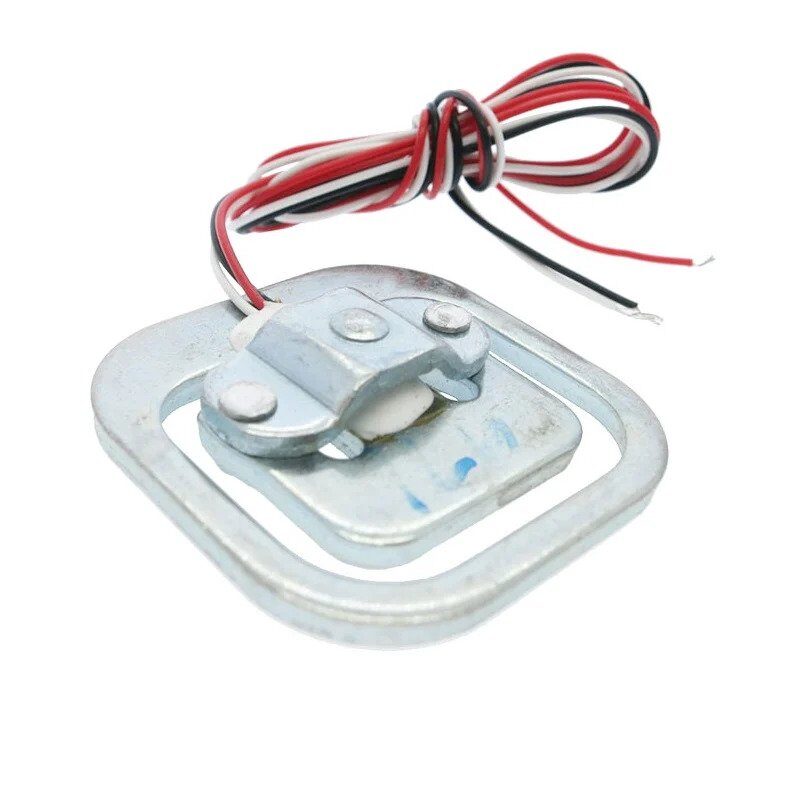
50kg Half-bridge Body Scale Load Cell Sensor
Half-bridge load cell for bathroom scales and body weight experiments. Pairs with HX711 for DIY weighing applications.
Error Sources and Compensation
Temperature Effects
Temperature changes the resistance of strain gauges independently of strain. Constantan alloy has a very low temperature coefficient of resistance (TCR), but for high-accuracy applications, a full Wheatstone bridge arrangement (where all four gauges experience the same temperature) provides the best self-compensation.
Creep
Under constant load, the strain gauge output slowly drifts (creeps) as the adhesive and backing relax. Quality load cells specify a creep rate in %FS/30 minutes. For dynamic force measurements (weighing), this is rarely a problem, but for static structural monitoring it must be accounted for.
Hysteresis
The output for a given load may differ slightly depending on whether the load is increasing or decreasing. This is due to mechanical friction and viscoelastic effects in the adhesive. Quality load cells specify hysteresis as a percentage of full scale (%FS).
Cable Resistance
In long cable runs, the cable resistance adds to the excitation and signal paths. Use a 6-wire configuration (with sense wires) for cable lengths above 10 metres, or a cable with 4 shielded twisted pairs.
Electrical Noise
The millivolt-level signals from a load cell are susceptible to electromagnetic interference (EMI). Always use shielded cables, keep signal wires away from power cables, and add a 100 nF capacitor across the HX711 power supply pins.
Real-World Applications
- Digital weighing scales: Kitchen scales, luggage scales, postal scales — all use full-bridge load cells with HX711 or similar ICs.
- Industrial force monitoring: Press force monitoring, bolt tension measurement, tension control in winding machines.
- Robotics: Gripper force feedback, compliant joint torque sensing, tactile sensing arrays.
- Structural health monitoring: Bridge strain measurement, building settlement monitoring, landslide early warning systems.
- Biomedical: Prosthetic limb force sensing, rehabilitation equipment force feedback, gait analysis force plates.
- Agriculture: Grain bin weight monitoring, silo load cells, automatic feeder control by weight.
Frequently Asked Questions
Q: What is the difference between a strain gauge and a load cell?
A strain gauge is the sensing element — a foil resistor that changes resistance under strain. A load cell is a complete transducer assembly: it includes a machined spring element, four strain gauges bonded in a Wheatstone bridge configuration, and protective housing. You buy a load cell; a strain gauge is what’s inside it.
Q: Why is a Wheatstone bridge better than a simple voltage divider?
A simple voltage divider would require measuring an absolute voltage and subtracting a reference — introducing errors from reference instability. The Wheatstone bridge measures the difference between two voltage dividers, inherently rejecting common-mode noise, temperature drift, and supply voltage variations. The bridge output at zero load is ideally exactly 0 V, which allows the amplifier to use maximum gain without saturation.
Q: Can I use a load cell with ESP32 instead of Arduino?
Yes. The HX711 uses a simple 2-wire interface that works with any GPIO-capable microcontroller. The HX711 Arduino library also works on ESP32. Connect DT and SCK to any two GPIO pins and use the same code — just change the pin numbers.
Q: How do I choose between a 1 kg and 10 kg load cell?
Choose a load cell rated 20–30% above your expected maximum load. For kitchen scale projects measuring up to 500 g, a 1 kg load cell is ideal. For package weighing up to 5 kg, use a 10 kg cell. Overloading a load cell beyond 150% of its rated capacity can permanently damage it.
Q: What does mV/V mean on a load cell datasheet?
mV/V (millivolts per volt) is the load cell sensitivity specification. A 2 mV/V load cell powered by 5 V excitation produces a maximum output of 10 mV at full rated load. With a 5 V supply, a 3.3 mV/V cell produces 16.5 mV maximum. The HX711 with 128× gain amplifies this to approximately 1.28 V at the ADC input.
Conclusion
The combination of strain gauge theory and the Wheatstone bridge provides an elegant and powerful method for precise force measurement. From a simple 1 kg kitchen scale to a multi-tonne industrial weighbridge, the underlying physics remains the same: a foil resistor changes resistance proportionally to applied strain, a bridge circuit converts that resistance change into a measurable voltage, and a precision ADC like the HX711 digitises it for your microcontroller.
Whether you are building a postal scale, a robotic gripper with force feedback, or a structural monitoring system, understanding strain gauge theory gives you the knowledge to select the right load cell, configure the bridge correctly, calibrate accurately, and compensate for real-world error sources.
Ready to Build Your Force Measurement Project?
Zbotic stocks a full range of load cells (1 kg, 10 kg, 50 kg) for every project scale. Pair with an HX711 module and an Arduino or ESP32 for a complete weighing solution.


Add comment