
Stepper motors are the backbone of precision motion control in 3D printers, CNC machines, robotic arms, and DIY automation projects. But walk into any electronics store or browse online and you will quickly notice that stepper motors come with different numbers of wires — 4, 6, or even 8. Each configuration has a distinct internal winding arrangement, and picking the wrong one (or wiring it incorrectly) can lead to a motor that vibrates without rotating, overheats, or simply does nothing at all.
This guide breaks down every stepper motor wiring type in plain language, with connection diagrams, driver compatibility notes, and practical tips so you can confidently wire any stepper motor you encounter.
How Stepper Motors Work Internally
A stepper motor moves in discrete angular steps by energising electromagnetic coils in a specific sequence. Unlike a brushed DC motor that spins freely when you apply voltage, a stepper motor moves one precise step per electrical pulse — typically 1.8° (200 steps/revolution) for standard NEMA17 motors.
Inside every stepper motor are two or more coils wound around a toothed iron core. The number of external wires depends on how those coil windings are connected inside the motor housing:
- Two independent coils, four ends exposed → 4-wire bipolar motor
- Two coils with centre taps, six ends exposed → 6-wire unipolar/bipolar motor
- Two coils with both ends AND centre taps, eight ends exposed → 8-wire motor (most flexible)
The coil sequence that the driver energises determines whether the motor steps forward or backward. This is why correct wiring is non-negotiable — a miswired coil pair causes the motor to fight itself rather than rotate.
4-Wire Bipolar Stepper Motors
What it is
A 4-wire stepper motor has two coils (A and B), each with two terminals — making four wires total. There are no centre taps. The driver must reverse current direction through each coil to achieve stepping, which is why these are called bipolar motors.
Wire colour conventions
Wire colours vary between manufacturers, but a common arrangement is:
- Red — Coil A, terminal 1 (A+)
- Blue — Coil A, terminal 2 (A−)
- Green — Coil B, terminal 1 (B+)
- Black — Coil B, terminal 2 (B−)
Some motors use yellow/orange or different conventions. Always verify with a multimeter (see the identification section below).
Pros and cons
- Pros: Higher torque for the same motor size (full coil magnetisation), simpler wiring, smaller connector footprint
- Cons: Requires an H-bridge driver capable of reversing current; cannot be driven directly with simple transistor arrays
Typical applications
NEMA17 motors used in 3D printers (Ender-3, Prusa i3, Voron) are almost always 4-wire bipolar. Drivers like A4988, DRV8825, and TMC2208 are designed exclusively for bipolar motors.

NEMA17 5.6 kg-cm Stepper Motor with Detachable Cable
A classic 4-wire bipolar NEMA17 with detachable cable and D-type shaft — perfect for CNC, 3D printing, and precision motion projects.
6-Wire Unipolar Stepper Motors
What it is
A 6-wire stepper motor has two coils, each with a centre tap wire brought out. This gives you: A1, A-centre, A2, B1, B-centre, B2 — six wires total. Because the centre tap is connected to a reference voltage (usually positive supply) and only one half of each coil is energised at a time, the driver never needs to reverse current direction. This is the unipolar mode of operation.
Three ways to connect a 6-wire motor
- Unipolar mode (use all 6 wires): Connect centre taps to the positive supply rail. Drive the outer wires low through simple transistors (like ULN2003). Easiest to implement, but only half the winding is used at once — reduced torque.
- Bipolar series mode (use only 4 wires, ignore centre taps): Leave the centre taps disconnected. Connect A1/A2 and B1/B2 to a bipolar driver. Full winding in series means higher torque but lower max speed (higher inductance). Best for slow, high-force applications.
- Bipolar parallel mode (use all 6 wires, join differently): Connect A1 and A-centre together as one terminal; A2 is the other terminal. Same for B. This halves inductance, doubles max speed, but needs a driver that can supply double the current. Best for high-speed applications.
Identifying centre taps
Measure resistance between all wire pairs. The centre tap has half the resistance to each coil end compared to end-to-end resistance. Example: if end-to-end is 40Ω, centre tap reads 20Ω to each end.
8-Wire Stepper Motors & Universal Wiring
What it is
An 8-wire motor exposes every terminal of both half-windings independently. Internally there are four separate coil sections (two per phase). This gives maximum flexibility because you can connect them in series, parallel, or unipolar configurations.
Connection options
| Mode | How to Connect | Best For |
|---|---|---|
| Bipolar Series | Join A2+A3 → A-terminal; A1=+, A4=− | High torque, low speed (CNC) |
| Bipolar Parallel | Join A1+A3 → one terminal; A2+A4 → other | High speed, balanced current |
| Unipolar | Join A2+A3 as centre tap; use all 8 wires | Simple transistor drivers |
| Half Coil | Use only A1, A2, B1, B2 (one half each) | Very high speed, low torque |
8-wire motors are typically found in larger NEMA23 and NEMA34 motors used in industrial CNC machines and high-performance 3D printers.
Identifying Wires with a Multimeter
When you receive a motor without documentation, here is a systematic process to identify the wiring:
- Set multimeter to resistance (200Ω range).
- Test all pairs: Touch probes to every possible wire combination. Two wires with measurable resistance belong to the same coil; two wires with infinite (OL) resistance are on different coils.
- Group the wires into coils. For a 4-wire motor you will find two pairs. For 6-wire, you find two groups of three (or one pair and two pairs including centre taps).
- Find centre taps (6-wire/8-wire): Within a group, the wire that reads half the end-to-end resistance to both other wires is the centre tap.
- Verify by spinning: Connect one coil pair to a 3V supply through a 100Ω resistor and momentarily touch. You should feel a slight cog step. If the motor gets hot without stepping, you have a short or wrong pairing.
Pro tip: Many NEMA17 motors list coil resistance in their datasheet. If the datasheet says 3.4Ω per coil and your measurement is 6.8Ω between two wires, those are the two ends of one coil in series.
Choosing the Right Driver
For 4-wire bipolar motors
- A4988: Up to 2A per phase, microstepping up to 1/16. Budget-friendly, available everywhere. Ideal for NEMA17 in 3D printers.
- DRV8825: Up to 2.2A, microstepping up to 1/32. Slightly quieter than A4988.
- TMC2208/TMC2209: Ultra-quiet StealthChop mode, UART configuration, sensorless homing. Premium choice for 3D printing.
For 6-wire motors in unipolar mode
- ULN2003 module: Darlington transistor array, handles up to 500mA per channel. Pairs perfectly with the 28BYJ-48 stepper.
- L293D / L298N: H-bridge driver, can run 6-wire motors in either unipolar or bipolar mode.
Current setting formula (for bipolar drivers)
Most drivers have a VREF potentiometer. The formula is:I_limit = VREF / (8 × R_sense)
Always set current 10–20% below the motor’s rated phase current to reduce heat and extend life.

A4988 Stepper Motor Driver Controller Board (Red)
The most popular driver for 4-wire bipolar steppers — supports 1/16 microstepping, built-in thermal shutdown, and easy STEP/DIR interface for Arduino/ESP32.
Practical Wiring Tips & Common Mistakes
Tip 1: Never disconnect a stepper while powered
Disconnecting a stepper motor while the driver is powered can generate a back-EMF spike that destroys the driver IC instantly. Always power down the system or disable the driver before disconnecting motor wires.
Tip 2: Swap one coil pair if the motor goes backwards
If your motor spins in the opposite direction from what the software expects, simply swap the two wires of coil A (swap A+ and A−). Do not change the software — this is always the correct hardware fix.
Tip 3: Heat is your enemy
Stepper drivers run hot because they continuously supply current even when the motor is stationary (holding torque). Use heatsinks, set current limits properly, and enable current reduction features when the motor is idle.
Tip 4: Keep motor wires away from signal wires
Stepper motor cables carry switched currents that generate EMI. Route them away from sensor cables, I2C/SPI lines, and encoder wires. Use twisted pairs where possible.
Tip 5: Use capacitors on the power supply
A 100µF electrolytic capacitor across the motor supply at each driver helps absorb voltage spikes from motor switching transients and protects your driver from overvoltage damage.
Common mistake: Wrong coil pairing on 8-wire motors
On an 8-wire motor configured for bipolar series, connecting A1+A4 together (same coil end) instead of A2+A3 (middle junction) results in counter-wound coils that cancel each other — the motor will vibrate but not rotate. Always trace winding order from the datasheet.
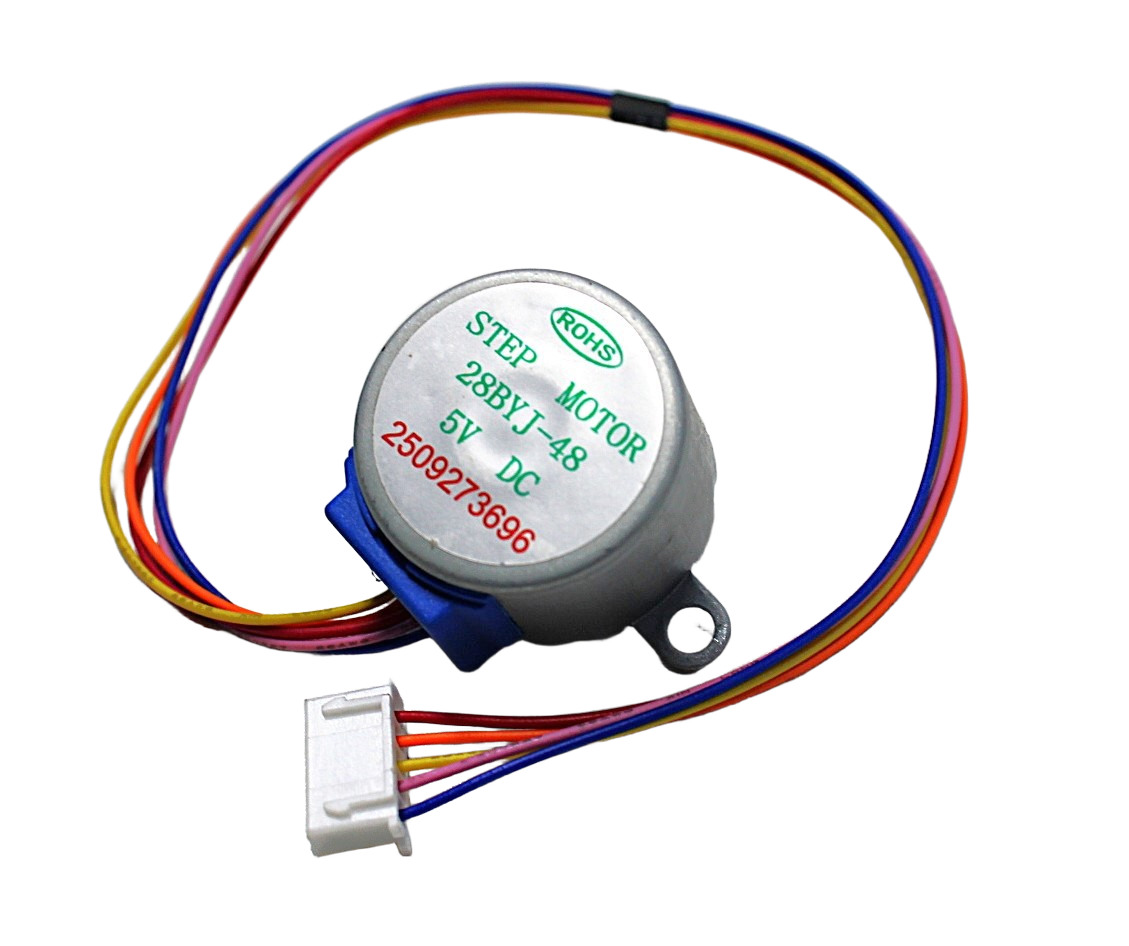
28BYJ-48 5V Stepper Motor
The classic 5-wire unipolar geared stepper — great for beginners learning stepper motor wiring, and ideal for pan/tilt rigs and low-load automation projects.
Recommended Stepper Motors & Drivers from Zbotic
Zbotic stocks a curated range of stepper motors and compatible drivers for every project level — from beginner 28BYJ-48 kits to industrial-grade NEMA17 motors.
Frequently Asked Questions
What is the difference between a 4-wire and 6-wire stepper motor?
A 4-wire stepper is a pure bipolar motor with two coils and four terminals. A 6-wire stepper has the same two coils but adds a centre tap on each, giving six terminals. The 6-wire motor is more flexible — it can be driven in unipolar mode (simpler drivers) or bipolar mode (higher torque) by choosing which wires to use.
Can I use a 6-wire stepper with an A4988 driver?
Yes. Leave the two centre tap wires disconnected and connect the four outer wires to the A4988 just like a 4-wire bipolar motor. This uses the coils in bipolar series mode and gives you good torque at moderate speeds.
Why does my stepper motor vibrate but not rotate?
This usually means the two wires of one coil are swapped, so the motor is fighting itself. Use a multimeter to verify which wires belong to the same coil (they should show resistance between them). Also check that the step and direction signals from your controller are correct.
What is microstepping and does it affect wiring?
Microstepping divides each full step into smaller increments (1/2, 1/4, 1/8, 1/16, 1/32) by partially energising both coils simultaneously. It is handled entirely by the driver chip — wiring remains the same. Microstepping reduces noise and vibration but slightly reduces torque at each microstep.
How do I know what current to set on my stepper driver?
Check the motor’s datasheet for its rated current per phase. Set the driver’s current limit to that value (or 10–20% less for cooler operation). Use the VREF formula specific to your driver chip. Never exceed the rated current — it causes overheating and permanent magnet demagnetisation in severe cases.
Can an 8-wire stepper motor be used in a 3D printer?
Yes, if the motor’s frame size (NEMA17) and shaft dimensions match. Wire it in bipolar parallel mode for high speed or bipolar series mode for high torque, depending on your axis requirements. Ensure your driver can handle the increased current in parallel mode.
Zbotic stocks NEMA17 steppers, 28BYJ-48 kits, A4988 drivers, and more — all with fast shipping across India. Browse our Motors & Actuators collection and get your project moving today.


Add comment