
One of the most common questions from builders commissioning a new CNC machine, 3D printer, or robot is: “How fast can my stepper motor actually spin?” The answer is not a single number printed on the datasheet — it depends on your driver voltage, motor inductance, load inertia, microstepping setting, and the torque your application demands at speed. This guide provides the formulas, the reasoning, and practical tuning steps to find and exploit the true maximum speed of your stepper motor system.
Why Maximum Speed Is Limited
A stepper motor is a synchronous machine — it moves one step for every pulse it receives. At low speeds, each pulse arrives with enough time for the motor to complete the step and settle. As step frequency increases, the motor must build and collapse the magnetic field in each coil faster and faster. Since the coil is an inductor (resists changes in current), the current never reaches its rated value before the next step command reverses it. The result: available torque falls sharply at high speeds.
Eventually the available torque drops to zero — the motor can no longer accelerate and stalls. The step frequency at which this happens is the motor’s pull-out rate, effectively its maximum speed. Beyond this, the rotor cannot follow the rotating magnetic field and desynchronises.
Understanding the Torque-Speed Curve
Every stepper motor has a torque-speed curve — a graph of available holding/running torque versus step frequency. The shape is characteristic:
- Flat region (low speed): Torque is close to the holding torque rating. Current has time to reach rated value each step.
- Knee point: A frequency where torque begins to fall rapidly. This is determined by the motor’s electrical time constant L/R (inductance divided by resistance).
- High-speed falloff: Torque falls as approximately 1/f (inversely proportional to frequency). The motor can still step, but available torque shrinks.
- Pull-out point: Available torque equals load torque — the motor stalls.
The usable maximum speed for your application is where your load torque crosses the torque-speed curve — not the absolute pull-out point. If your load demands 50% of rated torque, you can only reach the speed where the motor still delivers 50% torque.

NEMA17 5.6 kg-cm Stepper Motor with Detachable Cable
A workhorse NEMA 17 motor — understanding its torque-speed curve helps you set maximum speed correctly in Marlin, GRBL, or any stepper firmware.
Inductance: The Real Speed Limiter
The motor’s winding inductance L (in mH) and resistance R (in Ω) together set the electrical time constant:
τ = L / R (seconds)
This is the time it takes for coil current to reach 63% of its final value after voltage is applied. To reach 99% of rated current requires about 5τ. At a step rate where the step period is shorter than τ, the current cannot reach rated value — and torque is proportionally reduced.
For a typical NEMA 17 motor:
- Inductance L ≈ 3–5 mH (per phase)
- Resistance R ≈ 2–4 Ω (per phase)
- τ = L/R ≈ 1–2 ms
At 200 steps/revolution, a step frequency of 1000 steps/sec = 300 RPM. With τ = 1 ms, the step period at 1000 steps/sec is 1 ms — exactly equal to τ. Current only reaches 63% of rated value, and torque is roughly 63% of rated. This explains why torque curve knees appear around 300–500 RPM for typical NEMA 17 motors on 12V supplies.
Effect of Supply Voltage on Max Speed
The stepper driver uses PWM to regulate current — it applies the full supply voltage until current reaches the target, then chops. Higher supply voltage means current rises faster:
i(t) = (V/R) × (1 - e^(-t/τ))
If V doubles (e.g., from 12V to 24V), the current rises twice as fast. At the same step frequency, the coil reaches rated current — maintaining full torque to higher speeds. This is the single biggest lever for increasing stepper maximum speed.
Doubling supply voltage approximately doubles the speed at which torque begins to fall — effectively doubling usable maximum speed. This is why 24V CNC machines consistently outperform 12V machines with identical motors.
Max Speed Calculation Formula
The empirical formula for estimating the step frequency at which torque drops to ~50% of rated (the practical knee point):
f_knee (steps/sec) ≈ V / (π × L × I_rated)
where:
  V       = supply voltage (Volts)
  L       = phase inductance (Henries — convert mH to H by dividing by 1000)
  I_rated = rated phase current (Amperes)
Above f_knee, torque falls roughly as f_knee / f. The pull-out frequency (absolute maximum) is approximately 5–10× f_knee depending on load inertia and friction.
For usable maximum speed with a safety margin (50% torque reserve):
f_max_usable ≈ 2 × f_knee
RPM_max = f_max_usable / (steps_per_rev / 60)
For 200-step/rev motor: RPM = f_steps × 60 / 200
Worked Example: NEMA 17
Motor specifications:
- Inductance: 3.5 mH = 0.0035 H
- Rated current: 1.2 A
- Steps/rev: 200 (full step), 3200 (1/16 microstepping)
- Supply voltage: 24 V
f_knee = 24 / (π × 0.0035 × 1.2)
       = 24 / 0.01319
       = 1819 steps/sec

f_max_usable = 2 × 1819 = 3638 steps/sec

In full-step (200 steps/rev):
RPM_max = 3638 × 60 / 200 = 1091 RPM

In 1/16 microstepping (3200 steps/rev):
RPM_max = 3638 × 60 / 3200 = 68 RPM
This is why high-speed CNC machines often use 1/4 or 1/8 microstepping rather than 1/16 — finer microstepping requires much higher step frequencies for the same RPM, pushing the controller into firmware speed limits and reducing available torque.

A4988 Stepper Motor Driver Controller Board
The classic A4988 supports up to 1/16 microstepping and runs efficiently at 12–36V — increasing your supply voltage directly boosts max stepper speed.
Microstepping & Max Speed Trade-offs
Microstepping has a direct effect on maximum mechanical speed because it multiplies the required step frequency:
| Mode | Steps/Rev | Steps/sec for 100 RPM | Torque vs Full-Step |
|---|---|---|---|
| Full step | 200 | 333 | 100% |
| 1/2 | 400 | 667 | 70% |
| 1/4 | 800 | 1333 | 50% |
| 1/8 | 1600 | 2667 | 35% |
| 1/16 | 3200 | 5333 | 25% |
For high-speed applications, consider using hardware microstepping interpolation. TMC drivers (TMC2208, TMC2209) accept 1/16 step signals from the controller and internally interpolate to 1/256 for smooth motion, giving you smooth low-speed operation without the high-speed penalty of running 1/256 natively.
Step-by-Step Tuning Procedure
Use this procedure to find and verify the maximum safe speed for your system:
Step 1: Set Vref correctly
Trim the driver’s Vref potentiometer for the correct phase current. For the A4988: Vref = I_rated × 8 × Rsense. For most red A4988 modules, Rsense = 0.1 Ω, so for 1.2 A: Vref = 0.96 V. Incorrect current setting ruins all subsequent tuning.
Step 2: Start at slow speed, note resonance zones
Run the motor from near-zero to maximum speed. Identify any resonance zones (buzzing, vibration at specific speeds). Note these speeds in steps/sec and later configure your firmware to accelerate through them quickly.
Step 3: Set maximum speed in firmware
In Marlin: DEFAULT_MAX_FEEDRATE and DEFAULT_MAX_ACCELERATION per axis. In GRBL: $110, $111, $112 (max rate in mm/min), $120, $121, $122 (acceleration). Start conservatively — 50% of your calculated maximum.
Step 4: Run high-speed test
Command a 100 mm move at maximum speed. Repeat 20 times. Check for stalls (motor doesn’t return to start position). If no stalls, increase max speed by 10% and repeat.
Step 5: Add load and re-test
A motor running perfectly unloaded may stall under normal operating conditions. Add the actual load (router spindle, print head, arm weight) and repeat Step 4 at 80% of the unloaded maximum.
Step 6: Set final maximum at 80% of stall speed
This 20% margin accounts for power supply voltage sag under load, temperature effects on motor resistance, and day-to-day variation. A stall during a long 8-hour CNC job is costly — always leave margin.
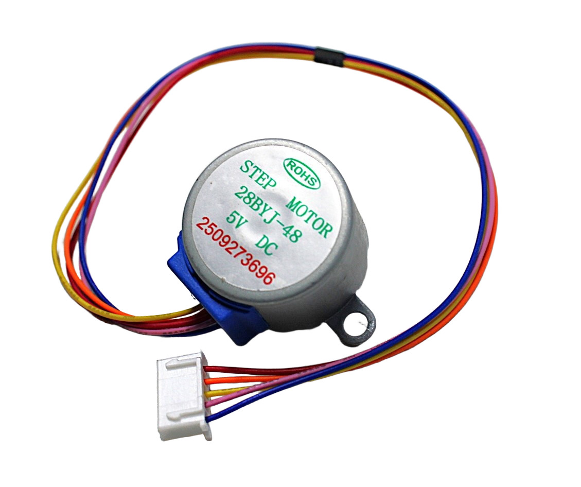
28BYJ-48 5V Stepper Motor
A classic 5V geared stepper for low-speed automation — its built-in 1:64 gearbox gives fine resolution at low speeds without needing high step frequencies.
Choosing the Right Driver & Voltage
Driver selection for speed
- A4988 (max 35V, 2A): Excellent at 24V. The cheapest path to higher max speed for NEMA 17. Supports up to 1/16 microstepping.
- DRV8825 (max 45V, 2.2A): Higher voltage headroom means more torque at high speed. Use with 24–36V supplies for CNC router work.
- TMC2209 (max 29V, 2A RMS): Best for 3D printers — StealthChop at low speed + SpreadCycle at high speed, hardware interpolation to 1/256, stall detection.
- TMC5160 (max 35V, 3A RMS): For NEMA 23 motors and demanding CNC axes. Requires SPI configuration.
Why 24V over 12V?
At 24V with an A4988 or DRV8825, the stepper motor current ramps up twice as fast, maintaining full torque to approximately twice the speed of a 12V supply. For a 3D printer converting from 12V to 24V PSU: axis maximum feed rates typically increase 50–100%, print speed improves, and the motors run cooler because the driver spends less time in chopper dissipation mode.
Frequently Asked Questions
What is the maximum speed of a NEMA 17 stepper motor in RPM?
With a 24V supply and a quality current-mode driver (A4988, TMC2209), most NEMA 17 motors can achieve 800–1200 RPM at minimal load. At 50% load torque, expect 400–600 RPM. The exact figure depends on the specific motor’s inductance — check your motor’s datasheet and use the formula in this guide.
Why does my stepper motor lose steps at high speed even with low load?
Resonance is the most common cause — the motor enters its resonance speed band and loses synchronisation. The second cause is insufficient supply voltage, making the current rise too slowly for the step period. The third is excessive microstepping generating step frequencies too high for the motor driver to output cleanly.
Does higher voltage damage the stepper motor?
No — stepper drivers use constant-current PWM control. The voltage only determines how fast the current rises, not the final current level. The driver always limits current to the Vref-set value. Using 24V or 36V with a motor rated for 12V is standard practice and does not damage the motor.
How does lead screw pitch affect maximum print/cut speed?
Maximum linear speed = max_RPM × lead_pitch. With a 2 mm pitch lead screw and 600 RPM max, maximum linear speed is 1200 mm/min. Switching to an 8 mm pitch (common in 3D printers) at the same RPM gives 4800 mm/min — 4× faster travel speed for the same motor speed.
Can I increase maximum speed by reducing microstepping mid-print?
Yes, but only with drivers that support dynamic microstepping changes without losing position (TMC drivers with hardware interpolation maintain position during microstepping changes). Abruptly changing A4988 MS pins during motion causes a position jump — only change between moves.
Build faster, more reliable motion systems. Zbotic stocks NEMA 17 stepper motors, A4988 and TMC drivers, and complete motor kits for 3D printers, CNC machines, and robotics — delivered across India.


Add comment