
Stepper motor drivers are among the noisiest components in any electronics project. The fast-switching MOSFET H-bridges in drivers like the A4988 and DRV8825 generate voltage spikes and high-frequency noise that propagate through the power supply, radiate from motor cables, and couple into adjacent circuits. The symptoms range from occasional encoder miscounts and random MCU resets to corrupted I2C communication and jittery sensor readings. This guide explains the physics behind stepper driver EMI and gives you practical, tested techniques to eliminate it.
EMI Sources in Stepper Systems
Understanding where EMI originates helps you target the right mitigation at each source. Stepper driver EMI has four main generation mechanisms:
1. Switching transients (conducted EMI): When the H-bridge MOSFETs switch at the PWM chopping frequency (typically 20–50 kHz), the abrupt current change through inductive motor windings creates voltage spikes (V = L × dI/dt). These spikes travel back up the power supply rail and can reach 40–80% above the nominal supply voltage for a few nanoseconds. If these reach the logic supply, MCUs reset.
2. Motor winding resonance (radiated EMI): The motor windings form an LC circuit with their distributed capacitance. At certain frequencies (often 100 kHz – 2 MHz for typical NEMA 17 motors) this circuit resonates, producing large oscillations on the motor current waveform. These current oscillations create a changing magnetic field that radiates from the motor leads like an antenna.
3. Ground plane currents: High-frequency currents from switching return through the common ground. If this ground is a thin wire or a narrow PCB trace, the impedance at high frequency (Z = jωL) creates a voltage difference between the motor driver ground and the MCU ground. This voltage difference appears as noise on any signal referenced to ground.
4. Capacitive coupling: The motor cables run near logic signal cables, sensor wires, or encoder cables. The mutual capacitance between them allows high-frequency noise to transfer from the motor circuit to the sensitive signal circuit even without direct electrical connection. This is particularly insidious because it is difficult to measure and often overlooked.
Common Symptoms of Stepper Driver EMI
Before applying mitigation, identify what type of interference you have:
- MCU resets during motor movement: Power supply noise is reaching the logic supply. The MCU’s internal brown-out detection circuit triggers a reset when supply voltage momentarily dips below the threshold. Cause: inadequate bulk capacitance on the motor supply rail.
- Encoder miscounts: Motor driver switching noise is coupling into encoder signal lines. Encoder pulses are being falsely triggered by noise spikes. Cause: shared ground impedance or capacitive coupling from motor cables to encoder cables.
- I2C/SPI communication errors: The I2C bus requires a stable pull-up voltage and clean logic transitions. Motor switching noise can corrupt bus data. Cause: ground bounce on the shared ground between driver and MCU.
- Stepper losing steps at high speed: Not always an EMI problem — can be torque rolloff. But if losing steps correlates with motor noise changing character (visible through current measurement), resonance is causing the driver’s current sense to misread, making it under-drive the motor.
- Analog sensor readings jumping: Particularly ADC readings from potentiometers, temperature sensors, or current shunts. Noise couples into the ADC input or ADC reference rail. Cause: shared analog ground contaminated by motor current return.

A4988 Stepper Motor Driver Controller Board
The benchmark STEP/DIR stepper driver. Includes the VMOT decoupling capacitor footprint — critical for noise suppression covered in this guide.
Bulk Bypass Capacitors: The First Defense
Bypass capacitors are the single most effective EMI mitigation for stepper drivers and should always be the first thing you add. They work by providing a low-impedance local energy reservoir that supplies the instantaneous current demand of each switching event, preventing the current from having to travel far down the power supply wires (which have their own inductance and resistance that create voltage drops).
The VMOT capacitor (most critical): Place a 100 µF electrolytic capacitor (35 V or higher rated) across the VMOT and GND pins of the driver board, as physically close to the driver as possible. This capacitor absorbs the back-EMF spike when the MOSFET turns off the motor winding. Without it, these spikes — which can be 40–80 V on a 24 V system — will destroy the driver. The Pololu A4988 datasheet explicitly warns: “The driver may be damaged by the voltage spike produced if it is connected to a motor without a large capacitor on the VMOT pin.”
High-frequency ceramic capacitor: Add a 100 nF ceramic capacitor in parallel with the 100 µF electrolytic. Electrolytics have parasitic inductance (ESL) that makes them ineffective above ~10 kHz. The ceramic capacitor has very low ESL and handles the high-frequency components of the switching transients that the electrolytic misses.
VDD (logic supply) bypass: Place 10 µF + 100 nF across the driver’s logic supply (VDD, typically 5 V). This prevents logic supply noise from affecting the driver’s control signals.
Multiple driver systems: Each driver needs its own 100 µF + 100 nF on VMOT. Do not share a single capacitor across multiple drivers — the high current spikes from each driver’s switching will partially cancel and partially add, creating complex noise patterns. One capacitor per driver, as close as physically possible.
Capacitor voltage rating: On a 12 V system, the peak VMOT spike can reach 20–30 V. Use 35 V rated capacitors as a minimum. On a 24 V system, use 50 V rated. The voltage rating is not about normal operating voltage — it is about surviving the worst-case spike.
Ferrite Beads and Common-Mode Chokes
A ferrite bead is a small bead of ferrite material threaded onto a wire or a surface-mount component soldered in series with a power or signal line. It has low impedance at DC and low frequencies (so it does not affect power delivery or signal integrity at normal operating frequencies) but high impedance at high frequencies (where it absorbs EMI as heat).
On the VMOT power lead: Add a ferrite bead (or a 4.7 µH power inductor) in series with the VMOT wire from the power supply to the driver board, before the 100 µF bypass capacitor. This forms an LC low-pass filter that blocks high-frequency noise from travelling back to the power supply rail and contaminating other boards connected to the same supply.
On motor phase wires (common-mode choke): Thread both wires of each motor coil pair through a single ferrite ring toroid. This creates a common-mode choke — it attenuates common-mode noise (noise that appears on both wires simultaneously and in the same direction, which is the type EMI tends to be) while passing differential-mode signals (the actual motor drive current, which flows in opposite directions on the two wires and is therefore differential). A single Fair-Rite #31 or similar ferrite ring with 3 turns of each motor wire pair provides 30–50 dB attenuation of common-mode noise above 1 MHz.
On encoder and sensor cables: A small snap-on ferrite clamp (available for flat cables and round cables) placed at the motor controller end of the encoder cable provides significant noise rejection. Place it as close as possible to the noise source (the driver board) rather than at the sensor end.
PCB Layout Rules for Low EMI
PCB layout is the most powerful EMI mitigation tool — effective layout eliminates the need for many external components. For custom PCBs or when designing a carrier board for stepper modules:
Separate power and logic ground planes: Use a solid copper pour for the motor power ground and a separate solid copper pour for the logic ground. Join them at a single point (star connection) near the power supply input. This prevents motor current return paths from creating voltage differences in the logic ground plane.
Motor current loop area: The motor current flows from the driver output, through the motor winding, and back to the driver. The area enclosed by this current loop is an antenna for radiated EMI. Route the motor phase wire pairs as closely twisted (or parallel on PCB) as possible to minimise this loop area.
Bypass capacitor placement: The bypass capacitor should be within 5 mm of the VMOT and GND pins, on the same layer, connected by wide short traces. Every millimetre of trace between the capacitor and the pins adds parasitic inductance that reduces the capacitor’s effectiveness at high frequencies.
STEP/DIR signal routing: Route STEP, DIR, and ENABLE signals away from motor phase traces and away from the power supply traces. If the PCB is two-layer, route logic signals on the top layer and power on the bottom, or use the ground plane as a shield between them.
Snubber circuits: For severe switching transients, place an RC snubber (10 Ω + 10 nF in series) across each motor winding output pair. The snubber absorbs energy from the inductive spike and converts it to heat in the resistor rather than a voltage spike. The values (5–20 Ω, 1–22 nF) depend on the motor’s inductance — a 1 mH motor coil with a 10 Ω / 10 nF snubber has a time constant of 100 ns, appropriate for suppressing spikes from a 50 kHz switching frequency.

NEMA17 5.6 kg-cm Stepper Motor with Detachable Cable
High-torque NEMA17 with detachable cable — easy to apply ferrite beads and snubbers to the cable assembly during EMI mitigation.
Motor Cable Shielding
Long motor cables (>30 cm) between the driver and motor act as effective antennas, both transmitting EMI to the environment and receiving external interference. Shielded cable dramatically reduces this radiation and pickup.
Cable type: Use shielded twisted pair (STP) for motor connections in sensitive environments. For a bipolar stepper motor with two coils (four wires), use two twisted pairs inside a common shield — each twisted pair carries one coil’s two wires. The twist reduces the differential-mode loop area; the shield provides a ground reference that intercepts common-mode noise.
Shield grounding: Ground the shield at one end only — the driver (noise source) end. Grounding at both ends creates a ground loop that can pick up low-frequency magnetic interference (50/60 Hz hum from power transformers nearby). Single-end grounding at the source connects the shield to the motor power ground right at the driver board.
Cable routing: Route motor cables away from signal cables. The minimum separation depends on frequency and cable length, but as a rule of thumb maintain at least 50 mm separation between motor cables and any analog or low-speed digital signal cables, or route them at 90° to each other to minimise the coupling area.
Conduit and metal enclosures: For industrial stepper applications, routing motor cables in steel conduit or inside metal cable trays provides significant shielding. The grounded metal enclosure acts as a Faraday cage, absorbing and redirecting the radiated energy to ground rather than into nearby electronics.
Grounding Strategy: Star Topology
Grounding is where many builders go wrong because it seems like all grounds are equal. At high frequencies they are not. Every ground wire has resistance and inductance. When motor return currents flow through a ground wire, they create a voltage proportional to the wire’s impedance at that frequency: V = I × Z = I × (R + jωL). This voltage appears as noise at every point on that ground conductor.
The star topology solves this: all ground connections return to a single central point (the power supply negative terminal) via separate paths. Motor return current takes its own path. Logic supply return takes its own path. Sensor ground takes its own path. Because paths do not share, there is no shared impedance voltage drop — motor return current noise does not appear on the sensor ground.
For breadboard builds where a star topology is impractical, apply these rules:
- Use the thickest wire available for motor power and return connections
- Connect sensitive electronics (MCU, encoder) to the ground bus at a point upstream (closer to the power supply) of where the motor connects
- Add 100 µF electrolytic + 100 nF ceramic to the MCU’s 5 V supply close to the MCU, in addition to the driver-side capacitors
- If using a voltage regulator for logic supply, use a 7805 linear regulator (which has good high-frequency rejection) rather than a noisy switching regulator on the same board as the drivers
Microstepping and Current Decay Mode
Microstepping significantly reduces EMI compared to full-step operation. In full-step mode, the motor current switches from full positive to full negative in one step — a very large, abrupt dI/dt. In 1/16 microstepping, the current changes smoothly in 16 small increments — much smaller dI/dt — which generates proportionally less EMI.
The A4988 supports 1, 1/2, 1/4, 1/8, and 1/16 microstepping via the MS1/MS2/MS3 pins. Setting MS1=HIGH, MS2=HIGH, MS3=HIGH enables 1/16 microstepping, which is the lowest-EMI setting. The tradeoff is 16× more steps per revolution (3200 steps for a 200-step motor), meaning the step rate (STEP pulses per second) must increase proportionally for the same rotation speed.
Current decay mode also affects EMI. The A4988 offers two current decay modes — fast decay and slow decay — selected by the DECAY pin (or automatically in mixed-decay mode on some versions). Fast decay produces sharper current waveforms (more EMI) but better high-speed torque. Slow decay produces smoother waveforms (less EMI) but can cause resonance at certain speeds. Mixed-decay mode (default on most drivers) is a good balance.
If you are experiencing resonance at specific motor speeds (a characteristic buzzing or vibration that disappears above and below a certain RPM), experiment with the decay mode setting. Some A4988 boards have a solder jumper for this; on bare-pin boards connect DECAY to either VREF or GND to force the mode.
Current Reference Tuning
Over-driving the motor current is a common EMI amplifier. The A4988’s VREF trimmer sets the peak current for the chopper. If VREF is set too high, the driver constantly hits the current limit, the chopper switches more aggressively than needed, and EMI increases with no benefit to torque (you cannot exceed the motor’s rated current usefully — the extra energy just becomes heat in the motor and extra noise).
Formula for A4988 current setting: I_max = VREF / (8 × R_sense). For the common red Pololu-style A4988 with R_sense = 0.1 Ω: I_max = VREF / 0.8. To set 1 A: VREF = 0.8 V. Measure VREF between the trimmer and GND with a small flat screwdriver on the trimmer and the red multimeter probe touching the trimmer body.
Set the current to the motor’s rated current, not higher. For a 28BYJ-48 (200 mA rated): VREF = 0.16 V. For a NEMA 17 at 1.2 A: VREF = 0.96 V. Reducing excess current reduces I²R heating in both motor and driver, reduces the switching current amplitude, and therefore directly reduces conducted and radiated EMI.
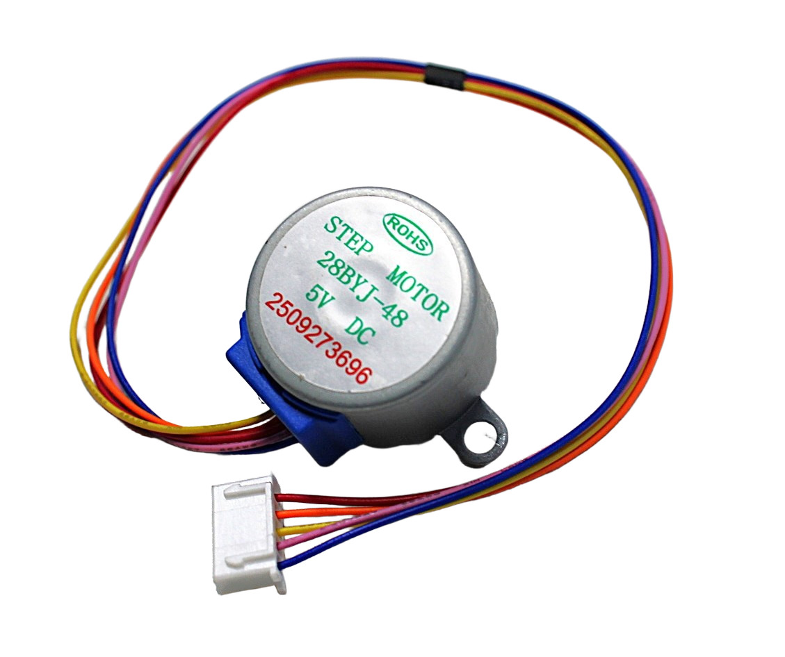
28BYJ-48 5V Stepper Motor
Entry-level stepper motor. Low rated current (200 mA) means very low EMI when properly driven — great for learning noise reduction on a forgiving platform.
Frequently Asked Questions
Why does my Arduino reset every time the stepper starts moving?
This is the most common stepper EMI problem. The back-EMF spike from the motor coil at the start of motion creates a voltage spike on the VMOT rail. If the 100 µF capacitor is missing or placed too far from the VMOT pin, this spike feeds back into the 5 V logic rail through the power supply’s internal coupling. Fix: add a 100 µF / 35 V electrolytic capacitor directly across the VMOT and GND pins of the stepper driver, as close to the pins as possible. Also add a 100 nF ceramic capacitor in parallel.
Does using a better stepper driver (DRV8825 vs A4988) reduce EMI?
Marginally. Both are MOSFET chopper drivers with similar switching architectures. The DRV8825 supports higher microstepping (1/32 vs A4988’s 1/16) which slightly reduces dI/dt. The DRV8825 also has better internal current regulation that reduces hunting around the setpoint. However, the dominant EMI mitigation factors (bypass capacitors, cable routing, grounding) matter far more than the choice between these two similar drivers.
How do ferrite beads help with stepper motor noise?
Ferrite beads have high impedance at the frequencies where stepper drivers generate noise (typically 100 kHz – 30 MHz). This high impedance reduces the amplitude of the noise currents that would otherwise flow through the power rails and ground wires. Unlike capacitors which store and release energy, ferrite beads dissipate the noise energy as heat in the ferrite material. This heating is negligible at typical signal levels but measurable in very high EMI environments.
Should I use a separate power supply for the stepper driver?
For sensitive analog circuits or precision measurement systems, yes. A dedicated motor power supply prevents switching noise from contaminating the logic supply. Use a linear regulator (7805, LM317) for the logic supply — linear regulators have excellent high-frequency noise rejection on their output and do not themselves generate switching noise, unlike buck converters. Connect the two supply commons together at a single point (near the motor driver board) and use the filtered linear regulator supply for all logic, MCU, and sensor circuits.
My stepper motor works fine on the bench but fails in the enclosure. Why?
Enclosures change thermal and electromagnetic conditions. Inside a metal enclosure, EMI that would radiate away is reflected and can re-enter the electronics at higher amplitude. Ensure the metal enclosure is properly grounded. Also check: the enclosure walls are not shorting any component, thermal conditions are adequate (drivers need airflow), and long motor cables inside the enclosure are not bundled next to logic cable bundles. Separating logic and power cables by at least 50 mm inside the enclosure usually resolves reflection issues.
What is the easiest first step to reduce stepper EMI on a breadboard?
Add a 100 µF electrolytic capacitor directly across VMOT and GND on the driver module, and a 100 nF ceramic in parallel. This single step eliminates the most dangerous EMI mechanism (back-EMF spikes reaching the logic rail) and resolves MCU reset issues in the vast majority of cases. After that, ensure the motor cables do not run parallel to signal wires. These two steps solve 80% of all stepper EMI problems encountered in hobbyist builds.
Build Clean, Reliable Stepper Projects with Zbotic
Zbotic stocks A4988 stepper drivers, NEMA17 steppers, and the 28BYJ-48 for every level of project. Get quality components that perform correctly with proper EMI mitigation.


Add comment