
Table of Contents
- Why Reading the Datasheet Matters
- Step 1: Identify the Motor Type
- Step 2: Step Angle and Steps Per Revolution
- Step 3: Rated Current and Phase Current
- Step 4: Phase Resistance and Inductance
- Step 5: Holding Torque and Detent Torque
- Step 6: Wire Count and Phase Identification
- Step 7: NEMA Frame Size and Mechanical Specs
- Step 8: Torque-Speed Curve
- Step 9: Temperature Ratings and Duty Cycle
- Selecting the Right Driver from Datasheet Values
- Real-World Example: Reading a NEMA17 Datasheet
- Recommended Products
- Frequently Asked Questions
- Conclusion
Why Reading the Datasheet Matters
A stepper motor datasheet is a one-page summary of everything the motor can do and everything it needs to work correctly. Ignoring it leads to the most common maker mistakes: burning out drivers, getting poor torque, experiencing step loss, or choosing the wrong power supply. Reading a datasheet is not complicated — it uses a standardised set of parameters that, once understood, unlock your ability to choose any stepper motor confidently.
This guide walks through every key parameter on a typical stepper motor datasheet and explains what it means, how it affects your circuit design, and what to look for when comparing motors. We use real values from NEMA17 motors — the industry standard for 3D printers, CNC routers, and robotics — to make the concepts concrete.
By the end of this guide, you will be able to look at any stepper motor datasheet and immediately identify: which driver to use, how to set the current limit, what voltage supply to choose, and whether the motor’s torque is sufficient for your mechanical load.
Step 1: Identify the Motor Type
Stepper motors come in several types, and the datasheet usually identifies the type by construction:
- Permanent Magnet (PM) Stepper: Uses a permanent magnet rotor. Lower torque but smoother motion. Common in small consumer devices (e.g., the 28BYJ-48). Typically 7.5°–15° step angles.
- Variable Reluctance (VR) Stepper: Soft iron rotor, no permanent magnet. No holding torque when de-energised. Rarely used in modern projects.
- Hybrid Stepper Motor: Combines PM and VR principles. High torque, small step angles (0.9° or 1.8°), excellent performance. This is what NEMA17 and NEMA23 motors are. Virtually all modern CNC and 3D printing steppers are hybrid.
The datasheet usually doesn’t say “hybrid” explicitly — it implies it through the step angle (1.8° is almost always a hybrid) and the performance specs (high torque, low resistance).
Step 2: Step Angle and Steps Per Revolution
The step angle defines how many degrees the motor shaft rotates per full electrical step. Common values:
| Step Angle | Steps Per Revolution | Typical Application |
|---|---|---|
| 0.9° | 400 | High-precision CNC, 3D printing |
| 1.8° | 200 | General purpose (most common) |
| 3.6° | 100 | Low-precision positioning |
| 7.5° | 48 | Consumer electronics, timers |
| 15° | 24 | Instruments, cameras (legacy) |
The step angle is also specified with a tolerance, typically ±5% (non-cumulative). Non-cumulative means the error doesn’t build up over many steps — a motor rated at 1.8° ±5% makes steps of 1.71°–1.89° but returns accurately to the same position after each full revolution.
How to use it: Steps per revolution × microstepping divisor = total steps per revolution for your system. Example: 200 steps × 1/16 microstepping = 3,200 microsteps per revolution. If your lead screw has a 2 mm pitch, you get 3,200/2 = 1,600 steps per mm for your CNC axis.
Step 3: Rated Current and Phase Current
The rated current (or phase current) is the most critical parameter for driver setup. It’s the current that flows through each motor winding in normal operation and determines the motor’s holding torque. Common datasheet labels:
- “Rated Current” or “Current/Phase” — in Amperes (A)
- “Drive Method” — indicates unipolar or bipolar (most modern motors are bipolar)
For a bipolar stepper motor (4-wire), the driver forces current alternately into each of the two phases. The rated current applies to each phase independently. A motor rated at 1.2 A/phase requires the driver to supply up to 1.2 A to each coil — it does not mean 2.4 A total simultaneously.
How to use it for A4988 driver setup:
Vref = Rated_Current × 8 × R_sense
For a 1.2 A motor with a standard A4988 board (R_sense = 0.1 Ω):
Vref = 1.2 × 8 × 0.1 = 0.96 V
Measure this voltage at the trimmer potentiometer wiper on the A4988 board with a multimeter. A common starting practice is to set to 70–80% of rated current to keep temperatures manageable, then increase if torque is insufficient.

NEMA17 5.6 kg-cm Stepper Motor (42HS48-1204A)
A well-documented NEMA17 motor with a full datasheet — perfect for practising datasheet reading: 1.2A/phase, 1.8° step angle, 5.6 kg-cm holding torque.
Step 4: Phase Resistance and Inductance
These two parameters describe the electrical behaviour of the motor’s windings and directly affect performance at speed.
Phase Resistance (R, in Ohms)
Measured with a multimeter between the two wires of one coil. Used to verify the motor is wired correctly (each coil should read the rated resistance). Also used to estimate power dissipation: P = I² × R. A 1.2 A motor with 1.5 Ω/phase dissipates 1.2² × 1.5 = 2.16 W per phase as heat.
Phase Inductance (L, in Millihenries)
Inductance is the key factor determining high-speed performance. Higher inductance means the coil current rises more slowly when voltage is applied — limiting how fast you can switch the motor at high step rates. The time constant τ = L/R tells you how quickly the coil reaches full current:
τ = L / R
A motor with L = 2.8 mH and R = 1.5 Ω has τ = 2.8/1.5 = 1.87 ms. At a step rate where you need full current within 0.5 ms, this motor will produce significantly less than rated torque at speed.
Solution: Higher supply voltage forces current to rise faster (the driver’s chopper circuit switches faster), compensating for high inductance. This is why running NEMA17 motors at 24 V dramatically improves high-speed performance even though the motor’s rated voltage is much lower (often just 2–4 V at rated current × resistance).
Step 5: Holding Torque and Detent Torque
Holding Torque is the maximum torque the motor can sustain at a given step position when the rated phase current is flowing and the shaft is stationary. It’s the motor’s maximum torque output and the primary specification for load-carrying applications. Expressed in N·m or kg-cm (1 N·m ≈ 10.2 kg-cm).
Critical caveats about holding torque:
- Holding torque is specified at rated current. Reduce the current (e.g., for heat management), and holding torque reduces proportionally.
- Holding torque drops sharply with speed. A motor’s holding torque is only available at zero speed. At 500 RPM, available torque might be only 20–30% of the holding torque value.
- Microstepping reduces per-microstep torque. At 1/16 microstepping, the torque available at each microstep position is approximately 30% of full-step holding torque.
Detent Torque (or Residual Torque) is the torque present when the motor is de-energised (no current in coils), caused by the permanent magnets attracting the rotor to preferred positions. Typically 10–20% of holding torque. You can feel this as the “clicks” when rotating the motor shaft by hand when disconnected. It helps the motor maintain position when power is briefly interrupted.
Step 6: Wire Count and Phase Identification
Stepper motors come in 4-wire, 6-wire, or 8-wire versions. The datasheet specifies the wiring configuration:
- 4-wire bipolar: Two coils, each with two wires (A+, A-, B+, B-). Only operates in bipolar mode. Most efficient and highest performance. All modern NEMA17 and NEMA23 motors use this.
- 6-wire: Two coils with a centre tap each. Can operate unipolar (4 phases, lower torque) or bipolar (ignore centre tap, same as 4-wire). The 28BYJ-48 uses a 5-wire unipolar design.
- 8-wire: Four coils (two per phase). Can be connected in series (higher inductance, better for high torque at low speed) or parallel (lower inductance, better for high speed). Maximum flexibility.
How to identify coil pairs without a datasheet: Use a multimeter in continuity or resistance mode. Two wires from the same coil will have the rated resistance between them (e.g., 1.5 Ω). Two wires from different coils will show infinite resistance (open circuit).
Step 7: NEMA Frame Size and Mechanical Specs
NEMA (National Electrical Manufacturers Association) frame sizes define the motor’s physical dimensions, especially the bolt hole pattern and faceplate size. The number is the frame size in tenths of an inch across the face:
| NEMA Size | Face Size (mm) | Bolt Hole Spacing | Typical Shaft Dia. |
|---|---|---|---|
| NEMA 8 | 20.3 × 20.3 | 16 mm | 4 mm |
| NEMA 11 | 28.2 × 28.2 | 23.1 mm | 5 mm |
| NEMA 17 | 42.3 × 42.3 | 31 mm | 5 mm (D-shaft) |
| NEMA 23 | 57.2 × 57.2 | 47.1 mm | 6.35 mm |
| NEMA 34 | 86.4 × 86.4 | 69.6 mm | 9.525 mm |
Additional mechanical specs to note from the datasheet:
- Shaft type: Round shaft (uses set screws and shaft collars) vs. D-shaft (flat on one side, better anti-rotation). The 42HS48-1204A has a D-type shaft.
- Rotor inertia: Important for high-acceleration applications. Higher inertia requires more torque to accelerate and decelerate.
- Axial and radial load ratings: Maximum force the shaft bearing can sustain. Exceeding these causes premature bearing failure.
Step 8: Torque-Speed Curve
The torque-speed curve (also called pull-out torque curve) is the most important graph on any stepper motor datasheet. It shows available torque on the Y-axis versus motor speed (in steps/second or RPM) on the X-axis. Most datasheets show this curve for different supply voltages.
Key features to read from the curve:
- Pull-in torque curve: Maximum torque at which the motor can start and stop without step loss (lower curve)
- Pull-out torque curve: Maximum torque the motor can sustain while already moving (upper curve)
- Slew region: The operating region between pull-in and pull-out curves. Motor must use acceleration to enter this region — cannot start from rest here without step loss
- Knee point: Speed at which torque begins to drop significantly. Below this speed, full holding torque is available. Above it, torque drops steeply.
For an A4988-driven NEMA17 at 12 V, the knee point is typically around 200–400 steps/second. Switching to 24 V pushes the knee point out to 600–800 steps/second, nearly doubling the usable speed range at full torque.
Step 9: Temperature Ratings and Duty Cycle
Datasheets specify:
- Ambient temperature range: Operating temperature range for the motor (typically -20°C to +50°C)
- Insulation class: Class A (105°C max coil temp), Class B (130°C), Class F (155°C). Most standard NEMA17 motors are Class B.
- Temperature rise: How much the coil temperature rises above ambient at rated current, continuous duty. A 50°C rise with 25°C ambient means coils reach 75°C — within Class B limits.
In practice, if your motor is too hot to touch for more than 1 second (above ~60°C surface temperature), consider reducing the driver current to 70–80% of rated, or adding forced air cooling. Motors can run hot and still be within spec as long as the coil temperature stays within the insulation class limit.
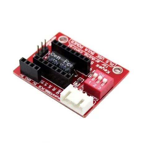
A4988 Stepper Motor Driver Controller Board (RED)
Set your motor’s phase current precisely using the A4988’s trimmer — now that you’ve read the datasheet, you know exactly what Vref to target for your motor.
Selecting the Right Driver from Datasheet Values
With the motor’s phase current and voltage ratings in hand, choose a driver that meets these requirements:
| Driver | Max Current | Max Voltage | Microstepping | Best For |
|---|---|---|---|---|
| ULN2003 | 500 mA | 50 V | None | 28BYJ-48 only |
| A4988 | 2 A | 35 V | 1/16 | NEMA17 ≤1.5 A |
| DRV8825 | 2.2 A | 45 V | 1/32 | NEMA17 high-current |
| TMC2209 | 2 A | 29 V | 1/256 | Quiet 3D printing |
| TB6600 | 4 A | 42 V | 1/16 | NEMA23, heavy CNC |
Selection rule: Choose a driver whose maximum current rating exceeds your motor’s rated phase current by at least 25%. This headroom protects the driver from thermal shutdown during acceleration peaks and ambient temperature variations.
Real-World Example: Reading a NEMA17 Datasheet
Let’s decode the key parameters of the 42HS48-1204A NEMA17 motor:
- Step Angle: 1.8° → 200 full steps per revolution
- Rated Current: 1.2 A/phase → Set A4988 Vref to 0.96 V (at R_sense = 0.1 Ω)
- Phase Resistance: 3.3 Ω → Measure with multimeter; current through coil at 12 V = 12/3.3 = 3.6 A (but driver limits this to 1.2 A via current chopping)
- Phase Inductance: 3.0 mH → τ = 3.0/3.3 = 0.91 ms (moderate; 12 V supply adequate for low-speed CNC)
- Holding Torque: 5.6 kg-cm → At 1.2 A rated current, can sustain 5.6 kg-cm load at standstill
- Weight: 330 g → Relevant for mobile robot inertia calculations
- Shaft: D-type 5 mm → D-shaft prevents slippage on pulley better than round shaft
- Frame: NEMA 17 (42 mm face) → Bolt holes on 31 mm square pattern, M3 screws
From these values: use A4988 at 0.96 V Vref, 12 V supply (24 V for faster motion), and expect reliable operation up to approximately 600 steps/second at the rated torque.
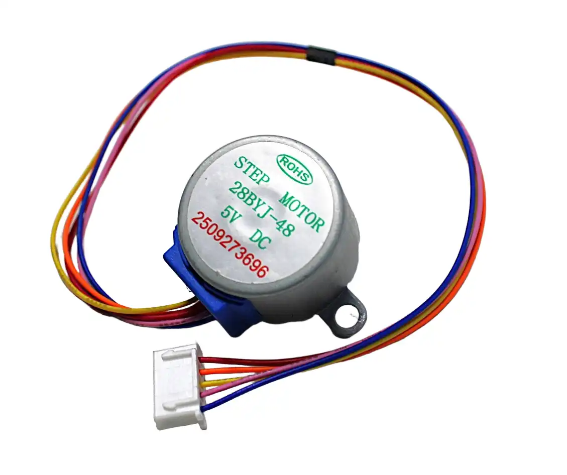
28BYJ-48 5V Stepper Motor
The beginner-friendly PM stepper with 7.5° step angle and internal gearing — a great motor to practise datasheet-reading with its simple unipolar wiring.
Recommended Products
Apply your datasheet knowledge to choose the right stepper and driver from Zbotic:
42HS48-1204A NEMA17 5.6 kg-cm Stepper Motor
A well-documented NEMA17 with 1.2 A phase current, 1.8° step angle, and 5.6 kg-cm holding torque. An ideal motor for practising datasheet-to-driver setup.
A4988 Stepper Motor Driver Controller Board (RED)
Perfect A4988 pair for the NEMA17: set Vref = 0.96 V for 1.2 A motors using the procedure described in this guide. Supports up to 1/16 microstepping.
Frequently Asked Questions
What does “bipolar” and “unipolar” mean in a stepper motor datasheet?
Bipolar steppers have two coils (4 wires). The driver reverses current direction through each coil to step. This gives higher torque but requires an H-bridge driver. Unipolar steppers have centre-tapped coils (5 or 6 wires). Current only flows in one direction per half-coil, requiring simpler driver circuits (transistors/ULN2003) but producing less torque. Modern makers almost always use bipolar motors with A4988/DRV8825 drivers.
How do I calculate the motor’s rated voltage from the datasheet?
Rated voltage = Rated current × Phase resistance. For a 1.2 A motor with 3.3 Ω resistance, rated voltage = 1.2 × 3.3 = 3.96 V. This is the DC voltage at which rated current flows. In practice, drivers operate at much higher voltages (12–24 V) and use current chopping to limit actual coil current to the rated value, enabling faster current rise and better high-speed performance.
What is the difference between holding torque and running torque?
Holding torque is the peak torque at standstill with rated current. Running torque (pull-out torque at speed) decreases as RPM increases. Datasheets typically show the torque-speed curve for running torque. For most positioning applications, you choose a motor where the running torque at your target speed exceeds your load torque with a 50–100% safety margin.
Why do some datasheets list torque in oz-in and others in N-m or kg-cm?
Conversion: 1 N·m = 10.2 kg-cm = 141.6 oz-in. Indian and Chinese datasheets commonly use kg-cm, US datasheets use oz-in, European and formal engineering specs use N·m. Always note which unit is used and convert to your preferred unit before comparing motors.
Can I run a 12V rated stepper motor at 24V?
Yes, and it’s actually recommended for better high-speed performance. The driver’s current limiting (set via Vref on A4988) prevents the motor from drawing more than rated current regardless of supply voltage. The higher voltage simply forces current to rise faster in the coils, maintaining torque at higher step rates. Stay within the driver’s voltage limit (A4988: 35 V, DRV8825: 45 V).
How do I find the datasheet for an unmarked motor?
Measure the motor: face size (NEMA number), shaft diameter, body length, and coil resistance. Search for those dimensions plus the motor color and connector style. If the motor has a part number printed on a label (often on the back face), search that directly. If still not found, measure rotor inertia indirectly by timing how long it takes to spin up under a known torque, and estimate holding torque by measuring the force to deflect the shaft with a spring scale.
Conclusion
Reading a stepper motor datasheet is a skill that pays dividends in every motor project you build. Once you can decode step angle, rated current, phase resistance, inductance, holding torque, and the torque-speed curve, you have everything needed to select the right motor, configure the driver correctly, choose an appropriate power supply, and predict system performance before building anything.
The most important takeaway: set your driver’s current limit based on the motor’s rated phase current, not by guess. That single action resolves the majority of stepper motor problems that hobbyists face.
Browse Zbotic’s full selection of stepper motors and drivers, each with specifications to help you make the right choice for your next CNC, 3D printing, or robotics project.


Add comment