
SPI Protocol Explained: Clock, MISO, MOSI & CS for Beginners
If you have been working with Arduino and want to connect faster peripherals like SD card modules, TFT displays, or high-speed ADCs, understanding the SPI protocol Arduino explained in plain language is the first step. SPI (Serial Peripheral Interface) is one of the fastest and most widely used synchronous serial communication protocols in embedded systems, and it is built right into your Arduino’s hardware. This guide breaks down every pin — Clock, MISO, MOSI, and CS — with real wiring diagrams, code examples, and practical tips tailored for Indian makers and students.
What Is SPI? Origin and Overview
SPI was developed by Motorola in the mid-1980s and has since become a de-facto standard for short-distance, high-speed communication between microcontrollers and peripheral chips. Unlike I2C which is two-wire, SPI uses four wires and operates in full-duplex mode — meaning data can flow in both directions simultaneously.
SPI is a master-slave protocol. The master (Arduino) controls the clock and initiates all communication. One or more slaves respond only when selected by their Chip Select (CS) line being pulled low. There is no addressing scheme like I2C — physical wires do the selection.
Key advantages of SPI:
- Extremely fast — commonly runs at 8–80 MHz (vs I2C’s 0.1–1 MHz)
- Full-duplex: simultaneous send and receive
- Simple implementation, no acknowledgement overhead
- No address conflicts — CS pin selects each device uniquely
- Widely supported by sensors, displays, memory chips, and ADCs
Drawbacks:
- Requires 3 shared wires + 1 dedicated CS wire per slave device
- No error detection or flow control built in
- Not suitable for multi-master setups
- More wires than I2C — can get messy with many devices
SPI Pins Explained: MOSI, MISO, SCK, CS
Understanding each SPI pin is crucial. Here is a detailed breakdown:
MOSI – Master Out Slave In: This is the data line from the Arduino (master) to the peripheral (slave). When the Arduino sends data to an SD card or display, it travels on the MOSI line. On Arduino Uno/Nano, MOSI is pin D11. On Mega, it is pin 51.
MISO – Master In Slave Out: This is the data line from the slave back to the master. When you read data from an SPI sensor or memory chip, it comes back on MISO. Arduino Uno/Nano: pin D12. Mega: pin 50.
SCK (or SCLK) – Serial Clock: The clock signal generated by the master. It synchronises data on both MOSI and MISO lines. All SPI slaves share this line. Arduino Uno/Nano: pin D13. Mega: pin 52. Higher clock speed = faster data transfer.
CS (or SS) – Chip Select (Slave Select): Each slave device needs its own dedicated CS pin. The master pulls CS LOW to activate a specific slave and HIGH to deactivate it. By default, Arduino uses D10 as SS, but any digital output pin can serve as CS for additional devices.
Quick reference — Arduino SPI pins:
| Pin | Uno/Nano | Mega | Function |
|---|---|---|---|
| MOSI | D11 | 51 | Master → Slave data |
| MISO | D12 | 50 | Slave → Master data |
| SCK | D13 | 52 | Clock signal |
| CS/SS | D10 | 53 | Select slave device |
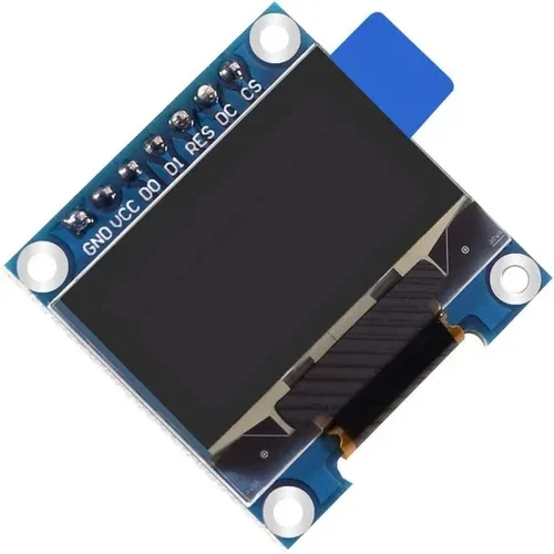
0.96 Inch SPI OLED LCD Module – 7-pin SSD1306 (White)
A perfect beginner SPI project — this 7-pin OLED uses MOSI, SCK, CS, DC, and RST. Great for learning SPI wiring hands-on with fast refresh.
SPI Clock Modes: CPOL and CPHA
SPI has four clock modes defined by two parameters: CPOL (Clock Polarity) and CPHA (Clock Phase). Getting the mode wrong is one of the most common beginner mistakes — your code will appear to run but the device responds with garbage data.
CPOL defines the idle state of the clock:
- CPOL=0: Clock idles LOW
- CPOL=1: Clock idles HIGH
CPHA defines when data is sampled:
- CPHA=0: Data sampled on the leading (first) clock edge
- CPHA=1: Data sampled on the trailing (second) clock edge
| Mode | CPOL | CPHA | Common Usage |
|---|---|---|---|
| 0 | 0 | 0 | Most common — SD cards, many sensors |
| 1 | 0 | 1 | Some ADCs, DACs |
| 2 | 1 | 0 | Some sensors |
| 3 | 1 | 1 | Some ICs, displays |
In Arduino code: SPI.beginTransaction(SPISettings(8000000, MSBFIRST, SPI_MODE0)) — always check your device datasheet for the correct mode.
Connecting Multiple SPI Slaves to Arduino
Unlike I2C, adding multiple SPI devices is straightforward — all share MOSI, MISO, and SCK, but each gets its own dedicated CS pin. The master controls which device is active by pulling only its CS pin LOW while keeping all others HIGH.
Wiring example with 3 SPI devices:
- All devices: MOSI → D11, MISO → D12, SCK → D13
- SD card module: CS → D10
- SPI OLED display: CS → D9
- SPI NRF24L01 radio: CS → D8
In code, before communicating with any device, pull its CS pin LOW and keep others HIGH:
const int CS_SD = 10;
const int CS_OLED = 9;
const int CS_RADIO = 8;

void setup() {
  SPI.begin();
  pinMode(CS_SD, OUTPUT);
  pinMode(CS_OLED, OUTPUT);
  pinMode(CS_RADIO, OUTPUT);
  // All CS HIGH = all deselected
  digitalWrite(CS_SD, HIGH);
  digitalWrite(CS_OLED, HIGH);
  digitalWrite(CS_RADIO, HIGH);
}

void talkToSD() {
  SPI.beginTransaction(SPISettings(4000000, MSBFIRST, SPI_MODE0));
  digitalWrite(CS_SD, LOW);  // select SD card
  // ... SPI.transfer() calls ...
  digitalWrite(CS_SD, HIGH); // deselect
  SPI.endTransaction();
}
Wiring an SPI OLED Display to Arduino
Let us walk through the complete wiring of a 7-pin SSD1306 SPI OLED to an Arduino Uno:
Pin connections:
- GND → GND
- VCC → 3.3V
- D0 (SCK) → D13
- D1 (MOSI) → D11
- RST → D8
- DC → D9
- CS → D10
Note: The SPI OLED is a write-only SPI device — it does not use MISO because the master never needs to read data back from the display. This is common for output-only peripherals like displays and DACs.
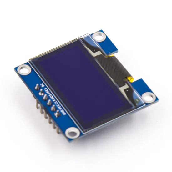
0.96 Inch SPI OLED LCD Module – 6-pin SSD1306 (Blue)
A compact 6-pin blue SPI OLED — great for beginners learning SPI wiring. Faster refresh than I2C variant, ideal for real-time data display.
Arduino SPI Code Examples
Here is a complete example using the Adafruit SSD1306 library with SPI:
#include <SPI.h>
#include <Adafruit_GFX.h>
#include <Adafruit_SSD1306.h>

#define SCREEN_WIDTH 128
#define SCREEN_HEIGHT 64
#define OLED_MOSI  11
#define OLED_CLK   13
#define OLED_DC    9
#define OLED_CS    10
#define OLED_RESET 8

Adafruit_SSD1306 display(SCREEN_WIDTH, SCREEN_HEIGHT,
  OLED_MOSI, OLED_CLK, OLED_DC, OLED_RESET, OLED_CS);

void setup() {
  if (!display.begin(SSD1306_SWITCHCAPVCC)) {
    Serial.println("SSD1306 init failed!");
    while (1);
  }
  display.clearDisplay();
  display.setTextSize(1);
  display.setTextColor(SSD1306_WHITE);
  display.setCursor(0, 0);
  display.println("SPI OLED Ready!");
  display.println("zbotic.in");
  display.display();
}

void loop() {}
Using raw SPI.transfer() for low-level control:
#include <SPI.h>

const int CS_PIN = 10;
byte receivedData;

void setup() {
  SPI.begin();
  pinMode(CS_PIN, OUTPUT);
  digitalWrite(CS_PIN, HIGH);
  Serial.begin(9600);
}

void loop() {
  SPI.beginTransaction(SPISettings(1000000, MSBFIRST, SPI_MODE0));
  digitalWrite(CS_PIN, LOW);

  SPI.transfer(0x9F); // read ID command (e.g., for flash memory)
  byte id1 = SPI.transfer(0x00);
  byte id2 = SPI.transfer(0x00);
  byte id3 = SPI.transfer(0x00);

  digitalWrite(CS_PIN, HIGH);
  SPI.endTransaction();

  Serial.print("ID: ");
  Serial.print(id1, HEX); Serial.print(" ");
  Serial.print(id2, HEX); Serial.print(" ");
  Serial.println(id3, HEX);
  delay(1000);
}
SPI vs I2C: When to Use SPI
Choosing between SPI and I2C comes down to your project’s speed, pin availability, and distance requirements:
- Use SPI when: You need high data throughput (displays, SD cards, fast ADCs/DACs, RF modules like NRF24L01), you have available GPIO pins, and devices are within 20–30 cm of the microcontroller.
- Use I2C when: You need to connect many sensors with minimal wiring, your GPIO is limited, and data rate is not critical (temperature sensors, RTC, OLED displays with modest update rates).

0.96 Inch I2C OLED LCD Module – 4-pin SSD1306 (White)
Compare I2C vs SPI by testing both OLED variants. This I2C version uses only 2 signal wires — ideal for projects where pin count is critical.
Pro Tips for SPI Projects
- Always use SPISettings: Wrap SPI transactions in
SPI.beginTransaction()/SPI.endTransaction()to safely share the bus and set speed/mode per device. - CS pin must be OUTPUT: Before calling
SPI.begin(), set your SS/CS pin as OUTPUT and pull HIGH, otherwise the Arduino may unexpectedly enter SPI slave mode. - Check voltage levels: Many SPI devices are 3.3V — the SPI OLED above needs 3.3V VCC. While signal levels often work at 5V tolerance on some devices, it is safer to use a level shifter or 3.3V Arduino (like ESP32) for sensitive devices.
- Daisy-chain mode: Some SPI devices (like shift registers) support daisy-chaining — the MISO of one device connects to MOSI of the next — allowing many devices with a single CS line. Check your device datasheet.
- Short wires at high speed: At 8 MHz+, keep SPI wires under 10 cm. At lower speeds (1 MHz), 30 cm is generally safe. Use twisted pairs for MOSI and SCK if possible.

Ai Thinker ESP32-C3-01M Wi-Fi + BLE Module
ESP32-C3 supports hardware SPI up to 80 MHz, far exceeding Arduino Uno’s 8 MHz. Great for SPI displays, SD cards, and wireless data logging.
Frequently Asked Questions
What is the maximum SPI speed for Arduino Uno?
Arduino Uno’s ATmega328P can drive SPI up to 8 MHz (half of its 16 MHz clock). In practice, 4 MHz is commonly used for stable operation over breadboard wires. ESP32 and STM32 boards support SPI up to 80 MHz for display-intensive applications.
Can MISO and MOSI be on the same wire?
No. MOSI and MISO are separate unidirectional lines for simultaneous full-duplex communication. Some devices only use MOSI (write-only like most OLEDs) or only MISO (read-only), but the two lines are never combined in standard SPI.
Why is my SPI device not responding?
Most common causes: wrong SPI mode (CPOL/CPHA), CS pin not driven LOW before transfer, SPI clock speed too high for the device, voltage level mismatch (3.3V device connected to 5V without level shifter), or SS pin on Arduino not set as OUTPUT.
Can I use SPI and I2C together on the same Arduino project?
Absolutely. They use completely different pins and can run independently. A common project combines an SPI SD card with I2C sensors — use SD.begin() for SPI and Wire.begin() for I2C simultaneously with no conflicts.
How many SPI devices can I connect to one Arduino?
There is no strict limit on the number of SPI slaves — you are only limited by available digital output pins for CS lines. On an Uno, you practically have 6–8 free pins for CS lines. On a Mega, you can connect 20+ SPI devices. Each device needs its own dedicated CS pin.
Ready to Build Your SPI Project?
Browse Zbotic’s range of SPI-compatible displays, sensors, and development boards. Fast shipping across India — get building today!


Add comment