
Soft-Start Circuit: Inrush Current Limiting for Power Supplies
A soft-start circuit for inrush current limiting is something every power electronics engineer eventually needs. The moment you flip a switch on a capacitor-heavy power supply, the capacitors demand an instantaneous rush of current that can be 10–50× the steady-state current. This inrush current blows fuses, trips breakers, welds relay contacts, and stresses transformer windings. A properly designed soft-start circuit ramps the voltage gradually, limiting inrush to safe levels. This tutorial walks you through the theory, practical designs, and ready-to-use modules for Indian hobbyists and engineers.
What is Inrush Current and Why Is It Dangerous?
When a power supply is first switched on, its bulk filter capacitors are fully discharged. From the perspective of the mains or DC source, these capacitors look like a short circuit for the first few milliseconds. The resulting current surge — inrush current — can easily reach 50–100A even in a modest 500W supply.
Real-World Consequences of Uncontrolled Inrush
- Blown fuses: Standard fuses rated for the supply’s operating current will rupture during startup. This forces over-rating the fuse, reducing short-circuit protection
- MCB (Miniature Circuit Breaker) tripping: Inrush current trips electromagnetic MCBs if the surge exceeds the B/C curve limits — frustrating in production environments
- Contact welding: Relay and switch contacts arc and weld during inrush events, particularly at 230V AC. A typical 5A relay may weld after just 100 inrush events
- Transformer saturation: In transformer-based supplies, inrush magnetisation current can be 5–20× rated current, causing loud acoustic noise and potential insulation damage
- EMI/line disturbance: High-frequency content in inrush spikes propagates through the mains network, causing interference with nearby equipment
In India, where power grid quality varies significantly between states, equipment that survives fine under stable utility power may fail repeatedly during voltage sags and re-energisation events — making inrush limiting even more critical.
How a Soft-Start Circuit Works
A soft-start circuit controls the rate of voltage rise at the power supply input, allowing capacitors to charge gradually rather than instantaneously. The charge current is limited to a safe level throughout the startup ramp.
There are three fundamental approaches:
- Series resistance: Insert a resistor in series with the capacitor during startup, then bypass it once charged. Simple, but resistor must dissipate P = I²R during startup
- NTC thermistor: Uses a negative temperature coefficient thermistor that has high resistance when cold (startup) and low resistance when hot (steady state)
- Active current limiting: A MOSFET or BJT in series with the load, controlled by an RC timing network, gradually increases conductance from zero to full on
NTC Thermistor Method: Simple but Limited
The NTC (Negative Temperature Coefficient) thermistor is the most commonly used inrush limiter in consumer electronics — you’ll find it in virtually every computer PSU and TV in the world.
How NTC Limiters Work
An NTC thermistor has resistance that decreases sharply as it heats up. At room temperature (25°C), a typical NTC for a 230V supply might have 10–47Ω resistance. This resistance limits the initial inrush current. As current flows through it, the thermistor self-heats to 100–120°C, dropping to 0.5–2Ω — negligible in steady state.
Selection Criteria for NTC Inrush Limiters
- R₂₅: Cold resistance at 25°C — determines inrush limiting. Higher = more limiting, but more initial voltage drop
- Imax: Maximum steady-state current the device can handle thermally
- Energy absorption capacity: Joules it can absorb during each startup event
Typical NTC selection for a 120W 12V SMPS (10A output): Use an NTC-5D-20 (5Ω, 20mm diameter, rated 8A continuous). This limits peak inrush from ~80A to under 15A while handling the 10A load current in thermal equilibrium.
NTC Limitations
The critical weakness of NTC limiters: if the power is cycled rapidly (off-on within 10–30 seconds), the thermistor doesn’t have time to cool down. On the second startup, it offers almost no resistance — essentially no inrush limiting. This is a known failure mode in equipment with automatic restart circuits.
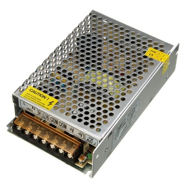
12V 10A SMPS – 120W DC Metal Power Supply
Quality SMPS with built-in EMI filter and inrush limiting. Ideal for powering LED strips, automation panels, and industrial control circuits. 120W output.
Active Soft-Start with MOSFET and RC Network
An active soft-start circuit overcomes the limitations of NTC thermistors by using a MOSFET in series with the power path, controlled by an RC timing network. The MOSFET gate voltage rises slowly with the RC time constant, gradually turning on the MOSFET and limiting current throughout the ramp.
Basic Circuit Topology
For a DC power supply soft-start:
- N-channel MOSFET in series with the positive supply line (or P-channel with inverted gate drive)
- Gate driven by RC network: R typically 100kΩ–1MΩ, C typically 1–100µF
- Time constant τ = RC determines startup ramp time
- Once fully on, MOSFET has negligible RDS(on) (typically 10–100mΩ)
Calculating Startup Time
The MOSFET starts conducting when VGS exceeds VGS(th) (typically 2–4V for logic-level MOSFETs). For a 12V supply with VGS(th) = 2V:
tstart = -τ × ln(1 – VGS(th)/VSupply) = -τ × ln(1 – 2/12) = 0.182τ
For τ = RC = 100kΩ × 47µF = 4.7s → soft-start begins ramping at t ≈ 855ms
In practice, for most SMPS applications, a 10–50ms soft-start ramp is sufficient. Use R = 100kΩ, C = 0.47µF for a ~47ms ramp.
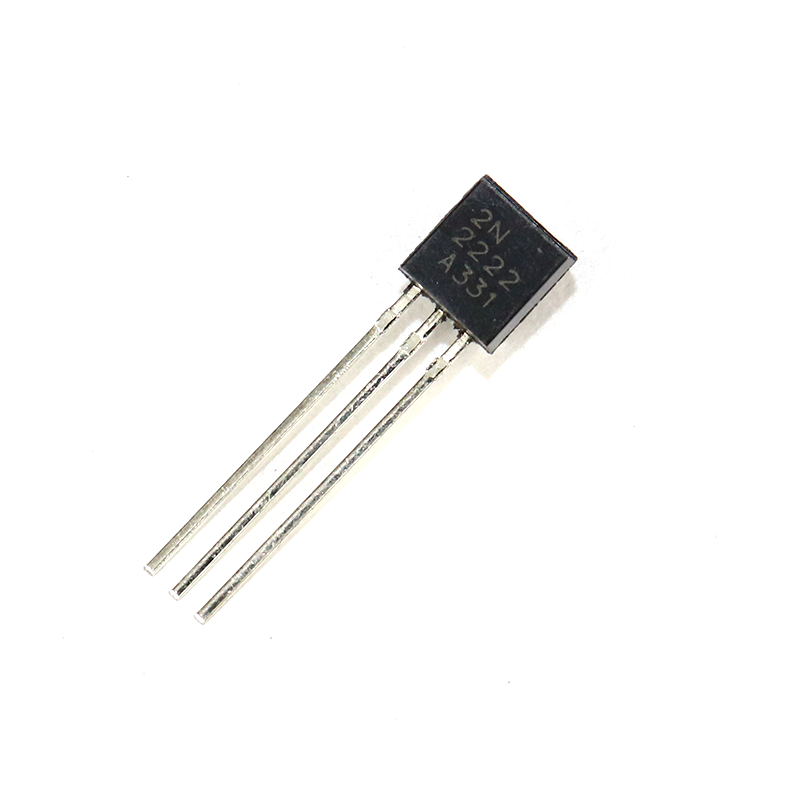
2N2222 NPN Transistor (Pack of 20)
General purpose NPN transistor for gate drive and signal amplification in soft-start control circuits. Pack of 20 for hobbyist projects and prototyping.
Soft-Start in SMPS Controllers
Modern SMPS control ICs (UC3842, SG3525, TL494, LM5020) include a dedicated soft-start pin (SS). This pin is connected to an internal current source that charges an external capacitor from 0V to the reference voltage. During this ramp, the PWM duty cycle is limited — preventing the transformer or inductor from saturating and the output from overshooting.
Configuring Soft-Start on UC3842
The UC3842 has a Soft-Start pin (pin 1 on DIP-8) with an internal current source of approximately 0.5mA. Connect a capacitor from this pin to GND:
- CSS = 1µF → soft-start duration ≈ 5ms (VSS ramps from 0 to 2.5V at 0.5mA/1µF = 2.5ms/V)
- CSS = 10µF → soft-start duration ≈ 50ms
- CSS = 47µF → soft-start duration ≈ 235ms (useful for supplies with large output capacitance)
The soft-start capacitor also determines loop stability during startup — too fast and you get output overshoot, too slow and the converter may hiccup in short-circuit protection mode before the output reaches regulation.
Practical Soft-Start Design for 12V SMPS
Here’s a practical soft-start circuit for a 12V, 10A DC SMPS using the bypass resistor + relay method — one of the most reliable approaches for AC-input power supplies:
Components
- NTC thermistor 10D-20 (10Ω cold, ~1Ω at operating temperature)
- 5V SPDT relay (coil powered from auxiliary 5V)
- Timer circuit: 555 in monostable mode or simple RC delay
- Protection diode across relay coil (1N4007)
Operation
- At power-on: NTC in circuit, relay NC contact open → all current flows through NTC thermistor
- After 500ms (RC delay): Relay energises, NO contact closes → NTC is bypassed, full current flows through relay contact
- NTC cools down within 60 seconds, ready for next startup cycle
This design avoids the NTC thermal memory problem since the relay bypass means the thermistor can cool fully between cycles. It adds ₹30–50 to the BOM but provides reliable inrush limiting regardless of cycle frequency.
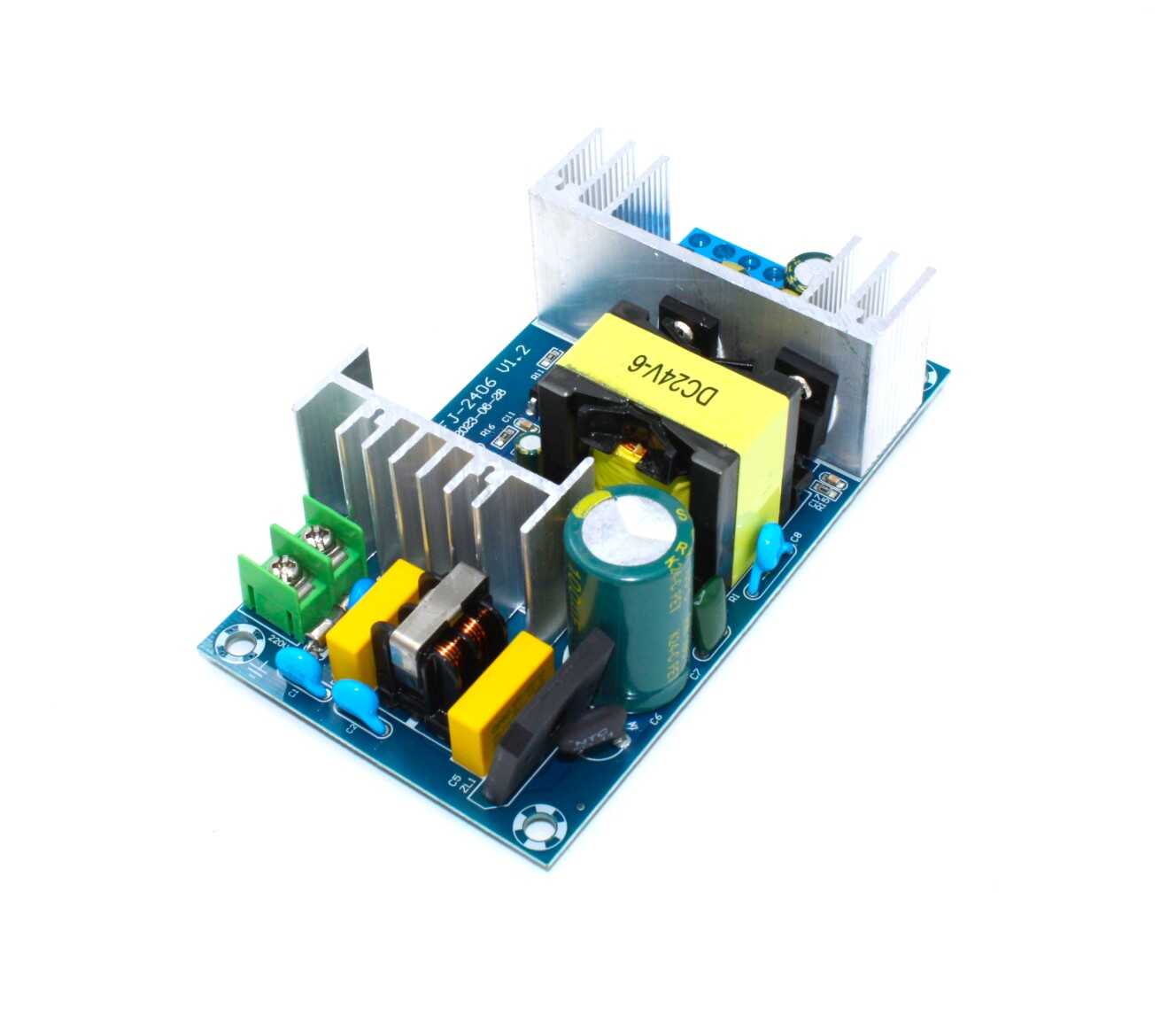
150W AC-DC Buck Converter 100V-240V to 24V
Compact AC-DC module with built-in soft-start and EMI filtering. Accepts Indian 230V mains, outputs regulated 24V DC at up to 9A. Ready-to-use module.
Testing and Measuring Inrush Current
Measuring inrush current requires an oscilloscope with a current probe or a shunt resistor in series with the power line. Here’s how to set up a budget-friendly test:
Shunt Resistor Method
- Insert a 0.01Ω (10mΩ) shunt resistor in series with the positive supply line
- Measure voltage across the shunt with your oscilloscope (Channel 1)
- Set time/div to 2–5ms to capture the full inrush event
- Calculate current: I = V / R_shunt. For 1V spike across 10mΩ → 100A inrush peak
Use an oscilloscope trigger set to the positive edge of the supply voltage to capture the startup transient. Most hobbyists have a 2-channel DSO — connect Ch1 to the supply output and Ch2 (via shunt) to the current.
Compare measurements before and after adding your soft-start circuit. A well-designed active soft-start should reduce peak inrush from 50–100A down to 2–5A for a typical 120W supply, bringing it comfortably within the fuse’s I²t rating.

LCR-T4 LCD Graphical Transistor/Component Tester
Measures resistance, capacitance, ESR, and identifies transistors automatically. Perfect for verifying component values in your soft-start circuit before assembly.
Frequently Asked Questions
How much does inrush current reduction matter for home workshop use?
For workshops in India with older wiring and individual MCBs per outlet, inrush limiting is very important. A 10A MCB will nuisance-trip on startup current if the supply draws more than 70–80A peak (for type B MCBs). Limiting inrush to under 30A ensures reliable startup even with type B MCBs.
Can I use a soft-start circuit with a battery charger?
Yes, particularly for lead-acid chargers connected to deeply discharged batteries (which look like short circuits). The soft-start ramps the charging current gradually, protecting both the charger’s output stage and the battery from thermal stress.
What’s the difference between soft-start and current limiting?
Soft-start is a time-based ramp at power-on only. Current limiting is a continuous protection that clamps current at any time during operation. A good power supply design includes both: soft-start for startup and cycle-by-cycle current limiting during fault conditions.
Can I add soft-start to an existing SMPS without modifying the PCB?
Yes — for DC outputs, add a series MOSFET on the output rail controlled by an external RC soft-start circuit. For AC input, add an NTC thermistor in series with the live conductor (ensure appropriate current rating). External soft-start modules are also available as complete assemblies.
What happens if the soft-start time is too long?
Excessively long soft-start can cause issues: the SMPS control loop may not reach regulation before the feedback circuit considers it a fault, triggering auto-restart. For most supplies, 10–100ms is appropriate. Servo drives and motor controllers may require 500ms to several seconds to allow mechanical loads to respond.
Build smarter power supplies! Zbotic stocks quality SMPS modules, buck converters, and passive components to help Indian makers and engineers design reliable power systems. Browse our Power Supply category for SMPS units, DC-DC converters, and all the components you need to protect your circuits from inrush damage.


Add comment