
Building a robot that spins continuously — a turret, a rotating sensor platform, a 360° camera gimbal — eventually hits the same fundamental problem: you cannot pass power and signals through a joint that rotates indefinitely using fixed wires. Within a few turns, those wires will twist and snap. The solution is a slip ring for rotating robot selection and wiring, a device that allows uninterrupted electrical continuity across a spinning interface. This guide explains everything from how slip rings work to selecting the right type and wiring it correctly in your build.
How Slip Rings Work
A slip ring consists of two main sections: a rotating rotor and a stationary stator. Conductive rings (usually made of copper alloys, brass, or precious metal alloys like gold or silver) are embedded in the rotor. Spring-loaded brushes on the stator press against these rings to maintain continuous electrical contact as the rotor spins. Each ring-brush pair forms an independent circuit channel — so a 6-channel slip ring can pass six separate signals or power lines simultaneously.
The brush material matters enormously. Carbon brushes are cheap and common for high-current applications, but they generate debris and have higher contact resistance. Precious metal brushes (gold-on-gold) have far lower resistance (often under 0.1 Ω per channel), generate no debris, and support high-frequency signals — essential for SPI, I2C, UART, or CAN bus in robotic applications. They are more expensive, but for control signals and sensor data, they’re worth it.
Types of Slip Rings
Capsule (Cylindrical) Slip Rings
The most common type in robotics. A compact cylindrical housing with the stator wires exiting from the flat end and the rotor shaft protruding from the opposite end. Easy to mount through a hollow shaft or in a through-bore configuration. Available in diameters from 6 mm to 50 mm. Typical specs: 2–24 channels, 1A–5A per channel, up to 300 RPM (some rated to 1,000 RPM).
Through-Bore (Hollow Shaft) Slip Rings
Have a hollow centre bore that lets you route a shaft, cable bundle, pneumatic hose, or optical fibre through the middle while the slip ring passes electrical signals around the perimeter. Ideal for robot arms where the main drive shaft must pass through the rotating joint. Bore diameters range from 5 mm to over 100 mm.
Pancake (Flat) Slip Rings
Flat disc-shaped design where rings are arranged concentrically on a flat face. Used when axial space is limited but radial space is available. Common in turntables and flat rotating displays. Generally not preferred for high-RPM applications due to uneven brush wear.
Ethernet / Fibre Optic Hybrid Slip Rings
For applications that need high-bandwidth data transfer (streaming video from a rotating camera at 1080p+), standard contact slip rings create signal degradation above a few MHz. Ethernet-rated slip rings use specially matched contacts and shielded channels for 100 Mbps Ethernet. Fibre optic rotary joints (FORJs) handle GHz bandwidth with zero electrical noise — but they cost significantly more.
Key Parameters to Evaluate Before Buying
- Number of channels: Count every electrical line crossing the joint: power +, power −, motor control, sensor data, ground, feedback. A 6-axis IMU connected to a rotating platform might need 4 channels (VCC, GND, SDA, SCL). Add 2 more for a servo signal and its ground for safety.
- Current rating per channel: Standard capsule rings handle 1A–5A. If you are passing motor current (e.g., 3A for a 30W DC motor), ensure each current channel is rated accordingly. Do not exceed 80% of the rated current continuously.
- Voltage rating: Most hobby slip rings handle 240–480 V AC/DC — far more than your 5V–24V robot needs. Still verify if using industrial voltage.
- Operating RPM: Continuous rotation speed. At higher RPMs, contact resistance increases and noise grows. A brushed ring rated 300 RPM should not be pushed above 250 RPM continuously.
- Contact resistance: Lower is always better for signal channels. Look for ≤0.05 Ω for data lines, ≤0.5 Ω for power lines. Higher resistance creates voltage drops and signal distortion.
- IP rating: For outdoor or humid environments, choose IP44 or higher. Most bare hobby slip rings have no IP rating — add a 3D-printed enclosure if needed.
Selection Guide by Robot Type
| Robot Type | Recommended Slip Ring | Min Channels |
|---|---|---|
| Rotating turret (servo-driven) | 6-channel capsule, 1A, precious metal | 4 |
| 360° LiDAR / ultrasonic scanner | 6-channel capsule, 1A, low-noise | 4–6 |
| Robot arm base joint (high torque) | Through-bore, 5A channels, 12-channel | 8–12 |
| Camera gimbal (HD video) | Ethernet-rated or FORJ | 4+ Ethernet |
| AGV (swivel caster with sensors) | Through-bore, 2A, low-profile | 4 |

ACEBOTT ESP32 5-DOF Robot Arm Kit Expansion Pack
A 5-degree-of-freedom robot arm kit where the base rotation joint can benefit directly from a through-bore slip ring — allowing continuous 360° rotation of the upper arm assembly without wire tangles.
Wiring Basics: Step-by-Step
A slip ring has two sets of wires: the stator leads (fixed, connect to your main electronics) and the rotor leads (rotate with the joint, connect to the components on the spinning side). Never mix them up — the rotor leads must be mechanically fixed to the rotating part.
- Plan channel assignments: Label each channel before soldering. Use a consistent colour code: red for power +, black for GND, yellow for signal 1, blue for signal 2, etc.
- Measure continuity with a multimeter: Before installation, verify each stator channel corresponds to the correct rotor channel by probing both ends. Rotate the rotor slowly while probing — resistance should remain stable (no spikes above 2× the rated contact resistance).
- Dedicate separate channels to power and signal: Never share a channel between a power rail and a data line. Use individual channels for VCC and GND for each subsystem.
- Twist signal wire pairs: On the rotor side, twist the signal wire with its ground return to reduce inductive coupling from motor currents.
- Secure rotor leads with a strain relief: The rotor leads must have slack to accommodate rotation without pulling on the slip ring body. Use a small zip-tie loop or a printed strain-relief bracket 20 mm from the lead exit point.
- Solder, do not clamp: The tiny leads on capsule slip rings are easy to damage. Use 30 AWG tinned wire, low-temperature solder (183°C), and apply heat for no more than 2 seconds per joint.
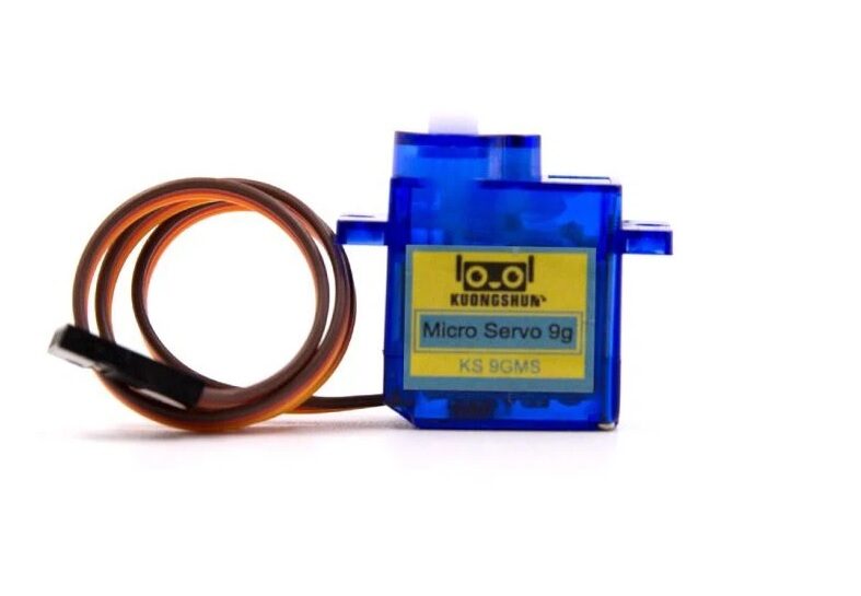
Servo SG90 9g 180 Degree
The go-to servo for lightweight rotating turret and pan-tilt mechanisms. Pair it with a 6-channel slip ring to pass VCC, GND, and PWM signal through the rotating joint — enabling unlimited continuous pan.
Signal Integrity and Noise Management
Slip ring contacts introduce resistance, capacitance, and sometimes arcing — all of which degrade high-frequency signals. Here’s how to mitigate problems:
- I2C (100 kHz–400 kHz): Works reliably through most precious-metal slip rings. Add 4.7 kΩ pull-up resistors on both sides of the ring. Keep total bus length (stator + rotor) under 1 metre.
- UART (up to 115,200 baud): Generally fine. Use ferrite beads on the signal leads at the slip ring exit point to suppress high-frequency noise from nearby motors.
- SPI (1–10 MHz): Borderline for contact slip rings. Use differential line drivers (RS-422) if your SPI device supports it, or switch to a lower-frequency protocol.
- PWM servo signals: 50 Hz is very low frequency — trivially compatible with any slip ring. No special measures needed.
- Power lines: Add a 100 µF electrolytic + 100 nF ceramic capacitor pair right after the rotor-side power output to filter contact bounce. This is critical for 5V logic circuits that react to brief voltage dips.
Common Mistakes and How to Avoid Them
- Over-tightening the stator housing: Capsule slip rings rely on the stator housing being fixed without mechanical stress on the internal brush assembly. Mount the stator to a bracket with gentle clamping — do not pinch the housing.
- Routing rotor leads through a tight radius: Bending the thin rotor leads at a sharp angle will fatigue and break them within hours of operation. Keep bend radius at least 10× the wire diameter.
- Ignoring RPM derating for high-current use: A ring rated 2A at 100 RPM may be limited to 1A at 300 RPM due to heat. Check the datasheet’s combined current × RPM specification.
- Using a single channel for both +V and GND: Each wire is a separate channel. Power positive and power negative need separate channels. Never attempt to share a ground through the chassis or frame.
- Forgetting to mechanically fix the stator: A slip ring stator that can rotate — even slightly — will progressively tighten the stator leads until they snap. Always clamp or bolt the stator firmly.
Mounting a Slip Ring in Your Robot
Most capsule slip rings include mounting flanges or a flat on the stator body. The standard approach is to 3D print a custom bracket that captures the stator’s anti-rotation flat and bolts to the robot frame. The rotor shaft either passes through a bearing (for supported rotation) or is pressed into the driven component directly.
For robot arms, the through-bore configuration is preferred: the drive shaft passes through the hollow centre, and the slip ring stator is bolted to the static link while the rotor is keyed to the rotating link. Zbotic’s ACEBOTT 5-DOF arm expansion kit uses servo-driven joints where adding a through-bore slip ring at the base enables full 360° waist rotation — a popular upgrade for pick-and-place automation projects.

DIY Acrylic Robot Manipulator Mechanical Arm Kit
Build your own multi-axis manipulator arm from acrylic panels. The base rotation joint is the ideal location to install a through-bore slip ring — enabling continuous 360° rotation for unlimited assembly-line style operation.
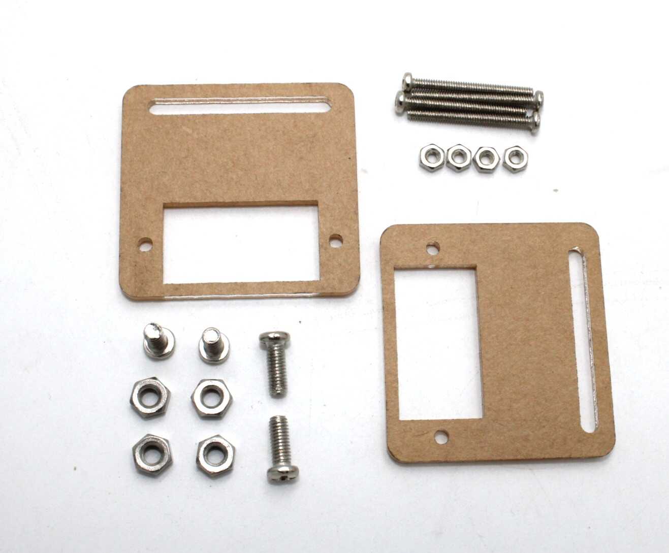
Servo Mount Holder Bracket For SG90/MG90 (Pack of 2)
Aluminium servo brackets that create the rotating joint for pan-tilt or turret mechanisms. A capsule slip ring mounts inside the bracket bore, passing servo control signals through the joint without wire wrap.
Frequently Asked Questions
How many channels do I need for a basic rotating sensor platform?
At minimum: VCC, GND, and one data line = 3 channels. In practice, buy a 6-channel ring — the extra channels cost very little and provide flexibility for future sensors or power redundancy.
Can a slip ring pass I2C signals?
Yes. I2C at 100 kHz or 400 kHz passes cleanly through precious-metal contact slip rings. Use pull-up resistors on both stator and rotor sides and keep the bus short.
What is the lifespan of a hobby slip ring?
Carbon brush rings: 500,000–2,000,000 revolutions. Precious metal rings: 10,000,000–100,000,000 revolutions. For a robot spinning at 10 RPM continuously, a carbon ring lasts roughly 35–140 days; a precious metal ring lasts years.
Can I use a slip ring with a stepper motor?
Yes, but stepper motor coils draw 1–2A per phase — ensure your slip ring channels are rated for the full coil current. A NEMA 17 typically needs 4 channels (A+, A−, B+, B−) for the coil wires plus 2 more for encoder feedback if used.
My slip ring crackles and the signal is noisy. What should I do?
First, clean the contact rings with isopropyl alcohol and a cotton swab while rotating. Second, add bypass capacitors on the rotor side. If noise persists, the brushes may be worn — replace the ring or contact the manufacturer for a brush kit.
From robot arm kits to servo brackets and motor controllers, Zbotic stocks everything you need to design and wire a continuously rotating robot joint — shipped fast across India.


Add comment