
A signal injector probe is one of the most underrated diagnostic tools in any electronics repair toolkit. While multimeters tell you DC voltages and resistances, a signal injector tells you whether signal can flow through your circuit at all. If you’re troubleshooting an audio amplifier that gives no output, an FM receiver that’s gone silent, or a CB radio with a dead front-end, signal injector probe troubleshooting techniques will save you hours of guesswork. This tutorial explains exactly how these tools work and how to use them effectively on both audio and RF circuits.
What Is a Signal Injector Probe?
A signal injector probe is a small handheld instrument that generates an electrical test signal — usually a square wave rich in harmonics — and injects it into a circuit at specific test points. By observing whether the signal appears (or is amplified) downstream, you can quickly isolate the faulty stage in an amplifier or receiver chain.
The basic signal injector produces a square wave at a fixed frequency, typically around 1 kHz for audio work. Because a square wave contains a fundamental frequency plus all its odd harmonics, it simultaneously covers audio frequencies from 1 kHz up to hundreds of kHz. This means a single injection point can stimulate stages tuned to different frequencies, making the tool valuable across audio, IF strip, and even low RF work.
More advanced injectors include a variable frequency oscillator (VFO), amplitude control, and selectable waveforms. But even a very basic injector built around a 555 timer or a simple transistor multivibrator is sufficient for diagnosing most consumer electronics faults.
How a Signal Injector Works
The signal injector operates on a deceptively simple principle: inject a known signal into a stage’s input; if the stage is good, the signal should appear (amplified or processed) at its output. If it doesn’t, the stage is the likely culprit.
Internal Circuit
Most signal injectors are built around a square wave oscillator — commonly a 555 timer IC in astable mode, or a CMOS Schmitt trigger inverter pair. The oscillator runs at a fixed frequency (often 1 kHz). The output is coupled through a small capacitor (typically 0.01 µF–0.1 µF) to a pointed probe tip. A series resistor (1 kΩ–10 kΩ) limits output current and prevents loading the circuit under test.
The signal is typically referenced to the circuit’s ground through a separate ground clip, which must be connected to the chassis or circuit GND before injecting anywhere.
Signal Richness
The beauty of a square wave for injection testing is harmonic content. A 1 kHz square wave contains components at 1 kHz, 3 kHz, 5 kHz, 7 kHz, and so on. If you’re testing an FM IF strip with a 10.7 MHz center frequency, you can inject at 1 kHz and the 10,700th harmonic (theoretically) would fall at 10.7 MHz — although the amplitude at that harmonic is very low. In practice, for RF stages you want an injector running at a higher base frequency, or you use a dedicated RF signal generator.
Troubleshooting Audio Circuits Step by Step
Audio troubleshooting with a signal injector is a systematic process. Always work backwards from the speaker to the input for the fastest isolation, or forwards from input to output depending on your preference. Backwards is usually faster because you can hear the result directly.
Step 1: Prepare the Circuit
Power up the amplifier or audio device under test. Set the volume to a medium level. Connect the injector’s ground clip to the circuit’s ground (chassis ground or the negative of the supply). Never inject signal without a ground reference — you’ll get unreliable results and potentially damage components.
Step 2: Inject at the Speaker
Touch the injector probe to the positive terminal of the speaker. You should hear a distinct buzz or tone from the speaker itself. If you don’t hear anything, the speaker is faulty or disconnected. This is your baseline — confirm the speaker and output wiring are good before going further.
Step 3: Inject at the Output Stage Input
Move back to the input of the final amplifier stage (the base of the output transistor or the input pin of the power amp IC). If you hear sound now, but didn’t from the driver stage output, the final stage is faulty.
Step 4: Work Back Stage by Stage
Continue moving the probe backwards through each stage — driver, pre-amp, tone control, volume pot input, phono/line input. At each point, injecting should produce louder output than the previous (downstream) point because each stage adds gain. The moment you inject and hear nothing (or very weak signal) while the next stage downstream worked, you’ve found the dead stage.
Step 5: Verify with Volume Control
The volume control pot is a useful checkpoint. Inject before and after the pot. If injecting before the pot produces sound that varies with the pot position, the pot is working. If injecting before the pot always gives full volume regardless of the knob, the pot is open or bypassed.
Stage-by-Stage Audio Diagnostic Table
| Injection Point | Expected Result | If No Sound |
|---|---|---|
| Speaker terminal | Buzzing from speaker | Speaker/wiring fault |
| Output IC input pin | Loud buzzing | Output IC or supply fault |
| Pre-amp output | Moderate buzzing | Driver/coupling stage fault |
| Volume pot wiper | Volume-controlled buzz | Pre-amp or tone stage fault |
| Input jack | Quietest buzz (full gain) | Input stage fault |
Troubleshooting RF Circuits
Applying signal injector probe troubleshooting to RF circuits requires a bit more care. RF stages have tuned circuits (LC tanks, IF transformers) and operate at much higher frequencies than the basic 1 kHz square wave injector output. However, the harmonic content of a square wave still makes it useful for IF strips and mixer stages.
AM Radio IF Strip
AM radios use a 455 kHz IF frequency. A 1 kHz square wave injector has harmonics at every odd multiple of 1 kHz — including 455 kHz (the 455th harmonic). Inject into the last IF transformer’s secondary; the demodulated audio should come through the speaker. Work backwards through each IF stage. When the stage that kills the signal is identified, suspect the IF transformer, transistor, or decoupling capacitors in that stage.
FM Radio IF Strip
FM IF is at 10.7 MHz. A 1 kHz injector’s harmonics at 10.7 MHz are very weak — a higher-frequency injector (around 100 kHz base frequency) works much better. Alternatively, use a proper RF signal generator if available. The diagnostic process is identical: start at the discriminator input and work backwards.
Practical RF Injection Tips
- Always couple the probe through a small capacitor (10 pF–100 pF) when injecting into tuned RF stages. Direct injection can detune the circuit or damage sensitive components.
- Keep injected signal amplitude low. High-amplitude injection can drive stages into saturation and produce misleading results.
- Be aware that your hand and the probe cable act as an antenna — keep the cable short and use a screened probe where possible.
- Work in a quiet RF environment. Nearby Wi-Fi and mobile signals can interfere with sensitive RF stages during injection tests.
Signal Injector vs Signal Tracer
A signal injector pushes a signal into the circuit; a signal tracer listens for signals already present in the circuit. Both techniques are complementary:
- Signal injection: Best when the circuit produces no output at all. Gives a clear go/no-go result at each stage.
- Signal tracing: Best when the circuit has distortion, noise, or partial output. Lets you follow the actual signal path and observe how it degrades stage by stage.
For complete diagnostics, use both techniques. Inject a known-good signal at the input and trace it forward. Wherever the signal stops or degrades excessively, that’s your fault location.
Recommended Tools from Zbotic
While the signal injector itself is the star of this workflow, several supporting tools from Zbotic make the diagnostic process faster and more accurate:
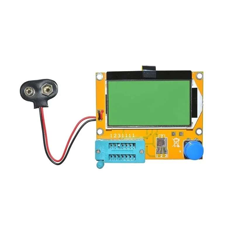
LCR-T4 Graphical Transistor & Component Tester
Once signal injection pinpoints a suspect stage, this component tester confirms whether transistors, capacitors, or resistors in that stage are defective. Tests ESR, hFE, capacitance and more out-of-circuit.

BC547 NPN 100mA Transistor TO-92 (Pack of 10)
Build your own 1 kHz square wave signal injector around the BC547. This classic NPN transistor is ideal for the two-transistor multivibrator oscillator at the heart of most DIY signal injectors.
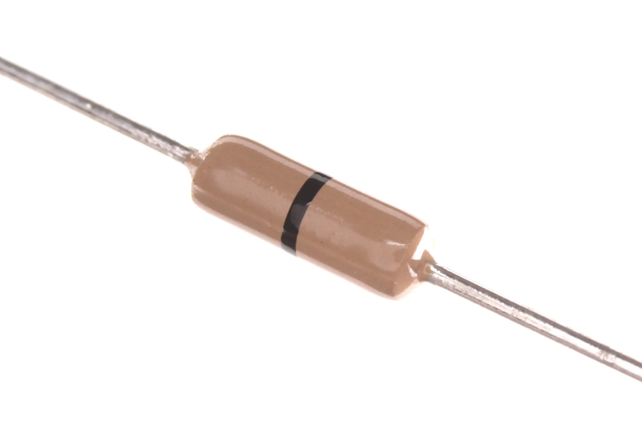
Assorted Carbon Film Resistors for DIY Signal Injector Build
A good signal injector needs precision resistors for the timing network and output attenuator. Carbon film resistors in assorted values give you the flexibility to set your injection frequency and output impedance correctly.

0.1/100nF Multilayer Ceramic Capacitor (Pack of 50)
The coupling capacitor in a signal injector is critical — it blocks DC and passes only the AC test signal. A 100 nF ceramic capacitor is the standard choice for audio-range signal injectors and bypassing in RF diagnostic circuits.
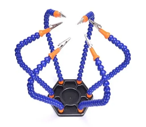
6 Flexible Arms Soldering Station With Swiveling Alligator Clip
Hold your circuit board steady with this flexible arm station while you inject signal with one hand and monitor with your meter in the other. Six arms with alligator clips provide the stability needed for precise fault isolation.
Pro Tips for Accurate Signal Injection
- Always connect ground first. Clip the injector’s ground lead to circuit GND before touching any active node with the probe tip.
- Use a series resistor. If your injector doesn’t have one built in, add a 1 kΩ–10 kΩ resistor in series with the probe tip to protect sensitive circuit nodes.
- Work at low supply voltages where possible. Reduce bench PSU voltage during injection testing to limit damage from shorts or unexpected circuit states.
- Document each injection point. Mark test points on a schematic printout as you go. It’s easy to lose track in a complex multi-stage amplifier.
- Don’t inject into IC output pins directly. Always inject at stage inputs, not outputs of active devices. Injecting into an op-amp output can damage the IC.
- Bypass the AGC during injection. Many RF receivers have Automatic Gain Control (AGC) that will reduce gain in response to the injected signal. Disable or bypass AGC for more consistent results.
Frequently Asked Questions
Can I use a signal injector to troubleshoot a completely dead amplifier?
Yes — and it’s one of the most effective situations for signal injection. Start by checking supply voltages with your multimeter, then inject at the speaker terminal to confirm the speaker is functional. Work backwards stage by stage to identify where signal flow stops.
What frequency should a signal injector output for audio work?
1 kHz is the standard frequency for audio signal injectors. It falls in the midrange of the audible spectrum and is easy to hear through a speaker. Some injectors offer 400 Hz, 1 kHz, and 10 kHz switch-selectable outputs for testing different stages.
Can I build my own signal injector?
Absolutely. A classic two-transistor multivibrator using BC547 transistors, two 10 kΩ resistors, and two 10 µF capacitors generates a 1 kHz square wave on a 9V battery. Add a series 4.7 kΩ output resistor and a 0.1 µF coupling capacitor and you have a functional signal injector for under ₹50 in components.
Is a signal injector the same as a tone generator?
There is overlap. A tone generator typically produces a clean sine wave output for audio testing. A signal injector usually produces a square wave specifically because the harmonic-rich output covers multiple frequency ranges simultaneously. For audio diagnostics, both work, but the injector’s square wave is more versatile.
Why doesn’t my signal injector work on RF circuits?
A 1 kHz base frequency injector produces very weak harmonics at RF frequencies. For FM IF at 10.7 MHz, you need a higher base frequency (100 kHz or higher) so fewer harmonic multiplication steps are needed to reach the test frequency. Alternatively, use a dedicated RF signal generator for systematic RF troubleshooting.


Add comment