
Table of Contents
- What Is a Reed Switch Magnetic Sensor?
- How a Reed Switch Works
- Types of Reed Switches
- Specifications and Ratings
- Project 1: Door Open Counter with Arduino
- Project 2: RPM Speed Meter with Reed Switch
- Wiring Diagrams and Circuit Notes
- Contact Bounce and Debouncing
- More Real-World Applications
- Frequently Asked Questions
What Is a Reed Switch Magnetic Sensor?
A reed switch is a magnetically-operated electrical switch contained in a small hermetically sealed glass envelope. Inside the glass tube, two thin ferromagnetic contacts (the “reeds”) are positioned close together but not quite touching. When a magnet is brought near the switch, the magnetic field magnetises both reeds and causes them to attract each other, snapping together to complete an electrical circuit. When the magnet is removed, the reeds spring back apart due to their natural elasticity, opening the circuit again.
This elegant, contact-free switching mechanism makes reed switches extraordinarily useful in a wide range of applications. They have no external moving parts (the reeds are sealed inside glass), require no external power to operate, switch extremely quickly (typically 0.1–1 millisecond), and can last for millions of cycles. They are immune to dust, moisture, and most chemicals because of the hermetic glass seal — making them suitable for environments where open mechanical switches would corrode or jam.
For Arduino makers, reed switches are most commonly used in two categories of application: event counting (door opens, passage counting, flow metering) and speed measurement (bicycle computers, motor RPM meters, conveyor belt speed monitors). This guide covers both applications with full wiring diagrams and Arduino code.
How a Reed Switch Works
The physics behind a reed switch is based on magnetism and ferromagnetism. The two internal contacts are made from a ferromagnetic alloy — typically a nickel-iron (Ni-Fe) alloy, often called permalloy or Mu-metal — chosen for its high magnetic permeability and low coercivity (it magnetises easily and demagnetises easily).
When no magnet is near, the reeds are held apart by their elastic spring force. A small air gap (typically 0.1–0.3 mm) separates them. When a permanent magnet is brought within the switch’s operating range (typically 5–30 mm depending on the switch type and magnet strength), the magnetic field lines pass through the glass envelope and through the reeds. The reeds become magnetised with opposite polarity at their tips, creating an attractive force that overcomes the spring force and snaps them together.
The critical magnetic field strength required to close the switch is specified as the Ampere-turns (AT) or Ampere (A) value. The field required to release (open) the switch is slightly lower than the closing field — this hysteresis prevents chattering when the magnet is near the threshold distance. This built-in hysteresis is one reason reed switches are more reliable than simple hall-effect comparators in vibration-prone environments.
Reed Switch vs Hall Effect Sensor
Both detect magnetic fields, but they work very differently. A hall-effect sensor is an active semiconductor device that produces an analogue voltage proportional to the magnetic field strength — it can detect field direction and magnitude. A reed switch is a passive mechanical device with only two states: open and closed. Hall sensors respond faster (microsecond response vs millisecond for reed switches) and produce no contact bounce, but require power and have a finite chip lifetime. Reed switches require no power, are extremely rugged, and can switch large currents that would damage a hall-effect sensor.
Types of Reed Switches
Normally Open (NO)
The default state is open (no circuit). A magnet closes the contacts. This is the most common type, used in door sensors (magnet on the door, switch on the frame — alarm triggers when door opens and magnet moves away).
Normally Closed (NC)
The default state is closed (circuit complete). A magnet opens the contacts. Less common; used where the safe condition requires current to flow and a magnetic field should interrupt it.
Changeover (SPDT)
Has three terminals: Common, Normally Open, and Normally Closed. In the absence of a magnet, the Common connects to NC. When a magnet is present, it connects to NO. Useful when you need to detect both presence and absence of a magnet with a single switch and drive two different circuits.
High-Voltage Reed Switches
Rated for operation at hundreds or even thousands of volts (with special contact spacing). Used in telecommunications, test equipment, and high-voltage measurement instruments.
Surface-Mount Reed Switches
SMD reed switches in miniature glass envelopes for PCB integration. Commonly found in laptop lid sensors, mobile phone flip detection, and wearable devices.

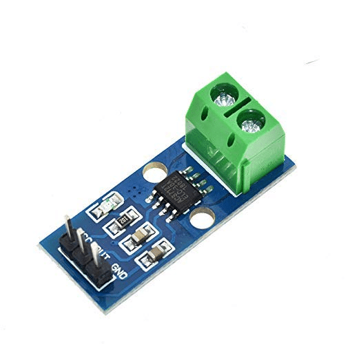
20A Range Current Sensor Module ACS712
Combine a reed switch speed sensor with an ACS712 current monitor to build a complete motor efficiency meter — measure both RPM and current draw simultaneously.
Specifications and Ratings
Key specifications to check when selecting a reed switch:
- Contact Form: NO, NC, or SPDT
- Operate Field (AT): Magnetic field (in Ampere-turns) required to close the switch. Lower AT = more sensitive = activates with weaker magnets at longer distances.
- Release Field: Magnetic field at which the switch opens. Always lower than operate field (built-in hysteresis).
- Operate Time: 0.1–2 ms typical
- Release Time: 0.05–1 ms typical
- Maximum Switching Voltage: Typically 100–200 VDC for standard switches
- Maximum Switching Current: 0.5–3 A for standard; up to 10 A for high-power versions
- Maximum Carry Current: Usually 2× the switching current rating
- Contact Resistance: <200 mΩ when closed
- Mechanical Life: >10⁸ operations (100 million cycles)
- Operating Temperature: -40°C to +70°C (standard); special versions to +150°C
Project 1: Door Open Counter with Arduino
A door open counter is the most classic reed switch project. It counts how many times a door, drawer, gate, or container lid is opened — valuable for retail foot traffic analysis, equipment usage logging, security auditing, and maintenance scheduling (e.g., replace a door seal every 10,000 openings).
How It Works
Mount the reed switch on the door frame and a small neodymium magnet on the door (aligned with the switch). When the door is closed, the magnet is directly opposite the switch, closing the contacts. When the door opens, the magnet moves away, the switch opens. The Arduino detects this transition (HIGH→LOW with internal pull-up, since the switch opens) and increments a counter.
Components
- Arduino Uno or Nano
- Reed switch (NO type)
- Small neodymium magnet (N35 or N52 grade, 10×5 mm disk works well)
- I2C OLED display (128×64, SSD1306) for counter display
- Push button (to reset the counter)
Wiring
- Reed switch terminal 1 → Arduino D2
- Reed switch terminal 2 → Arduino GND
- Enable
INPUT_PULLUPon D2 in code - Reset button → Arduino D4 (also INPUT_PULLUP)
- OLED SDA → Arduino A4 (SDA)
- OLED SCL → Arduino A5 (SCL)
Arduino Code
#include <Wire.h>
#include <Adafruit_SSD1306.h>

#define REED_PIN 2
#define RESET_PIN 4
#define SCREEN_WIDTH 128
#define SCREEN_HEIGHT 64
#define DEBOUNCE_MS 50

Adafruit_SSD1306 display(SCREEN_WIDTH, SCREEN_HEIGHT, &Wire, -1);

volatile unsigned int doorCount = 0;
int lastReedState = HIGH;   // HIGH = closed (door shut)
int lastReedRaw = HIGH;
unsigned long lastDebounce = 0;

void setup() {
  pinMode(REED_PIN, INPUT_PULLUP);
  pinMode(RESET_PIN, INPUT_PULLUP);
  Serial.begin(9600);
  display.begin(SSD1306_SWITCHCAPVCC, 0x3C);
  display.clearDisplay();
  display.setTextSize(2);
  display.setTextColor(WHITE);
  updateDisplay();
}

void updateDisplay() {
  display.clearDisplay();
  display.setCursor(0, 0);
  display.println("Door Opens:");
  display.setTextSize(3);
  display.setCursor(20, 30);
  display.println(doorCount);
  display.display();
}

void loop() {
  // Reset button
  if (digitalRead(RESET_PIN) == LOW) {
    doorCount = 0;
    updateDisplay();
    delay(500);
  }

  int rawState = digitalRead(REED_PIN);
  if (rawState != lastReedRaw) {
    lastDebounce = millis();
    lastReedRaw = rawState;
  }

  if ((millis() - lastDebounce) > DEBOUNCE_MS) {
    if (rawState != lastReedState) {
      lastReedState = rawState;
      if (lastReedState == HIGH) {
        // Door just opened (magnet moved away, switch opened → HIGH)
        doorCount++;
        Serial.print("Door opened. Count: ");
        Serial.println(doorCount);
        updateDisplay();
      }
    }
  }
}
This sketch counts each time the door opens (LOW→HIGH transition with pull-up), displays the count on an OLED, and allows a reset via a push button. In a retail environment, this gives you accurate daily foot traffic data.
Project 2: RPM Speed Meter with Reed Switch
A reed switch speed meter measures rotational speed (RPM) or linear velocity by counting magnetic pulses over time. Attach a small magnet to a rotating shaft, wheel, or disc. Each rotation brings the magnet past the fixed reed switch, generating one pulse per revolution. By counting pulses in a known time interval, you calculate RPM.
RPM = (pulse_count / time_seconds) × 60
For higher pulse resolution (and smoother RPM readings), use multiple magnets equally spaced around the rotating disc — each magnet gives one pulse per revolution, so the RPM formula divides by the number of magnets.
Components
- Arduino Uno or Nano
- Reed switch (NO type)
- 1–4 neodymium disc magnets (mounted on wheel/disc, equally spaced)
- 16×2 I2C LCD (or Serial Monitor for testing)
Speed Meter Arduino Code
#include <Wire.h>
#include <LiquidCrystal_I2C.h>

#define REED_PIN 2
#define MAGNETS 1           // Number of magnets on spinning disc
#define MEASURE_INTERVAL 1000  // Measure over 1 second window

LiquidCrystal_I2C lcd(0x27, 16, 2);

volatile unsigned int pulseCount = 0;
unsigned long lastMeasureTime = 0;
float rpm = 0;

void pulseISR() {
  pulseCount++;
}

void setup() {
  pinMode(REED_PIN, INPUT_PULLUP);
  attachInterrupt(digitalPinToInterrupt(REED_PIN), pulseISR, FALLING);
  Serial.begin(9600);
  lcd.init();
  lcd.backlight();
  lcd.print("Speed Meter");
  delay(1000);
  lcd.clear();
}

void loop() {
  if (millis() - lastMeasureTime >= MEASURE_INTERVAL) {
    // Atomically read and reset pulse count
    noInterrupts();
    unsigned int count = pulseCount;
    pulseCount = 0;
    interrupts();

    rpm = (count / (float)MAGNETS) * 60.0 * (1000.0 / MEASURE_INTERVAL);
    lastMeasureTime = millis();

    Serial.print("RPM: ");
    Serial.println(rpm, 1);

    lcd.setCursor(0, 0);
    lcd.print("RPM: ");
    lcd.print(rpm, 0);
    lcd.print("   ");  // Clear old digits

    float rps = rpm / 60.0;
    lcd.setCursor(0, 1);
    lcd.print("RPS: ");
    lcd.print(rps, 2);
    lcd.print("    ");
  }
}
Using an interrupt (FALLING edge — when the switch closes and pulls pin LOW) ensures no pulses are missed even at higher RPMs. The noInterrupts() block safely reads and resets the volatile counter without race conditions.
Maximum measurable RPM is limited by the switch’s operate/release time. A reed switch with 1 ms total operate+release time can theoretically switch 500 times per second (500 pulses/second = 30,000 RPM with 1 magnet). In practice, due to bounce effects, reliable RPM measurement tops out around 5,000–10,000 RPM with a reed switch. For higher speeds, use a hall-effect sensor.
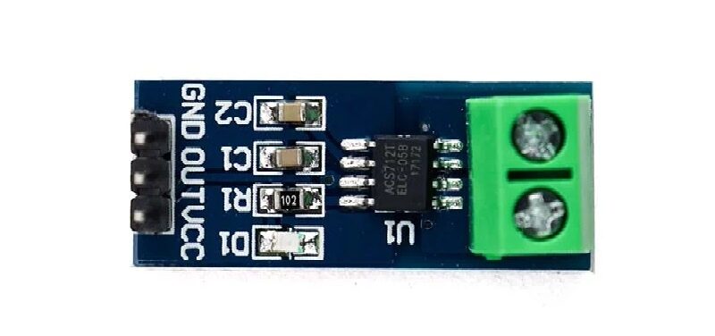
30A Range Current Sensor Module ACS712
Build a complete motor performance monitor: pair the reed switch RPM sensor with an ACS712 current sensor to calculate power consumption at each speed point.
Wiring Diagrams and Circuit Notes
Protection for Higher Voltages
When switching loads larger than what the Arduino can handle (anything above 40 mA on a GPIO pin), use the reed switch to drive a transistor or relay rather than connecting the load directly. For inductive loads (motors, solenoids, relay coils), always add a flyback diode across the load.
LED Status Indicator
Add a 5 mm LED in series with a 220 Ω resistor between the reed switch output and GND. This gives a visual confirmation that the switch is closing properly during installation and testing — extremely helpful when the magnet alignment is critical.
Long-Distance Installations
Reed switch cables can run several metres without signal degradation since the switch is essentially a passive resistor. However, long cables act as antennas and can pick up electromagnetic interference. Use shielded cable for runs over 3–5 metres, and ensure the shield is grounded at one end only to prevent ground loops.
Contact Bounce and Debouncing
Like all mechanical switches, reed switches exhibit contact bounce — rapid chattering of contacts on closing and opening. The duration is typically shorter than a mechanical button (0.1–5 ms for reed switches vs 5–20 ms for push buttons) but still long enough to cause false pulse counts in speed measurement or false door-opening events in counting applications.
For the door counter project, software debouncing with a 50 ms stable-state requirement eliminates bounce entirely. For the speed meter project, hardware debouncing via a 100 nF ceramic capacitor in parallel with the switch contacts is a simple and effective solution — it effectively low-pass filters the bouncing transitions. For very high speed switching, use a hall-effect sensor instead (no moving contacts = zero bounce).
Hardware Debounce Circuit
Connect a 100 nF ceramic capacitor from the switch pin (D2) to GND. This, combined with the internal pull-up resistor (~30–40 kΩ on Arduino), creates an RC low-pass filter with a time constant of approximately 3–4 µs. This eliminates bounce spikes while remaining fast enough for pulse counting up to several thousand RPM.
More Real-World Applications
Water Flow Meter
Turbine-type water flow meters contain a small reed switch that pulses once per revolution of the turbine. Water flow rate (litres/minute) = pulses per minute × volume per pulse (from sensor datasheet). Widely used in water dispensers, irrigation controllers, and industrial flow measurement systems.
Bicycle Speed Computer
Mount a reed switch on the front fork and a magnet on the wheel spoke. Count pulses per second, multiply by wheel circumference (metres), and you have speed in metres per second (multiply by 3.6 for km/h). This is exactly how traditional bicycle computers (cyclocomputers) have worked for decades.
Energy Meter Monitoring
Many older electromechanical energy meters (kWh meters) have a small disc that rotates at a rate proportional to power consumption. Some have a reflective spot or magnet on the disc. A reed switch or optical sensor reading this disc allows DIY energy monitoring without tapping into the electrical wiring.
Laptop Lid Sensor
Most laptops have a reed switch in the display bezel that detects when the lid is closed (via a magnet in the keyboard base). When closed, the laptop suspends. This is a reliable, zero-power-consumption sensor that has outlasted many other technologies in portable devices.
Security Alarm Door/Window Sensor
Every basic alarm system uses reed switch pairs — one switch on the frame, one magnet on the moving part. When the door or window opens, the magnet moves away, the switch opens, and the alarm triggers. Magnetic door contacts are sold in millions for home security applications globally.
Float Level Switch
A magnet mounted in a float housing slides past a vertically mounted reed switch as liquid level rises or falls. When the float reaches the switch level, it triggers — signalling high or low liquid level. Used in sump pumps, water tanks, chemical tanks, and aquarium auto-fill systems.
5A Range Current Sensor Module ACS712
Great companion for bicycle speed meter or small motor RPM projects. Measure the electrical power going into the motor alongside its mechanical speed output.
Frequently Asked Questions
How close does the magnet need to be to activate a reed switch?
This depends on both the switch sensitivity (operate field in AT) and the magnet strength. A strong N52 neodymium disc magnet (10 mm diameter, 3 mm thick) typically activates a standard reed switch at 5–20 mm distance. Weaker ferrite magnets may require 2–5 mm. Always test your specific magnet-switch combination to determine the reliable activation range, then mount with some safety margin (30–50% of the maximum activation distance).
Can I drive an LED or relay directly from a reed switch?
A standard reed switch can switch up to 1 A at 12 VDC — more than enough to directly drive an LED (with current-limiting resistor) or a small 5 V relay module coil (typically 50–100 mA). For larger loads (motors, high-current relays), use the reed switch to trigger a transistor (MOSFET or BJT) that then drives the load.
What type of magnet is best for reed switch applications?
Neodymium (NdFeB) magnets are the strongest permanent magnets available and are ideal for reed switch applications because they allow reliable activation over longer distances and through thicker materials (wood, plastic panels). N35 grade is the most common and cost-effective; N52 is the strongest commercially available grade. For harsh environments, epoxy-coated or nickel-plated neodymium magnets resist corrosion. Standard ferrite magnets work but require closer proximity.
Why does my reed switch read HIGH when the magnet is close?
If you are using INPUT_PULLUP and the switch is normally open (NO), the pin reads HIGH when the switch is open (no magnet) and LOW when the switch closes (magnet present). If you see HIGH with the magnet close, check that the switch is actually NO type (not NC), verify the magnet is aligned correctly with the switch axis, and confirm the wiring is correct (one terminal to pin, one to GND).
How do I calculate bicycle speed from reed switch pulse count?
Speed (km/h) = (pulse_frequency × wheel_circumference × 3.6). Wheel circumference = π × wheel diameter. For a standard 700c bicycle wheel (diameter ≈ 0.67 m), circumference ≈ 2.105 m. At 60 RPM (1 rotation/second with 1 magnet), speed = 1 × 2.105 × 3.6 = 7.58 km/h. At 120 RPM = 15.16 km/h. Easy to implement with the interrupt-based pulse counter code shown above.
Can a reed switch work in high-vibration environments?
Standard reed switches can be sensitive to shock and vibration — strong vibration can cause the glass envelope to crack or cause the reeds to chatter. For vibration-prone environments, look for ruggedised or shock-resistant reed switches with thicker glass envelopes and special contact coatings. Alternatively, in high-vibration applications, a hall-effect sensor is often more robust since it has no moving parts.
What is the difference between a reed switch and a reed relay?
A reed switch is just the glass-enclosed reed contacts — it requires an external magnet to operate. A reed relay adds an electromagnetic coil wound around the reed switch — energising the coil with a DC current generates the magnetic field to close the contacts. Reed relays are electronically controlled, allowing a microcontroller to switch isolated circuits. Reed switches are mechanically controlled by physical magnets.
The reed switch is one of the most underappreciated components in the maker’s toolkit. Its combination of zero standby power, mechanical simplicity, long lifespan, and complete immunity to dust and moisture makes it the ideal sensor for door counters, speed meters, flow meters, and level sensors. Paired with an Arduino and the interrupt-based code examples in this guide, you can build reliable, production-quality counting and measurement systems that will run for years without maintenance. Start with the door counter project and you will immediately appreciate the elegance of this timeless sensor technology.


Add comment