
The FC-37 rain sensor is a simple, affordable resistive sensor that detects the presence of water droplets on its sensing pad. When rain falls on the sensor’s nickel-plated PCB surface, it creates conductive bridges between the printed tracks, lowering the resistance and changing the output voltage. Paired with an Arduino, this sensor forms the backbone of automatic window closers, irrigation controllers, car wiper systems, weather stations, and outdoor equipment protection systems. This tutorial covers everything you need to build a working rain detection circuit with Arduino — from wiring to functional code with both digital and analog outputs.
How the FC-37 Rain Sensor Works
The FC-37 rain sensor operates on a simple resistive principle. Its sensing board is a PCB with a pattern of closely spaced, interleaved nickel-plated copper tracks. Normally (dry), these tracks are open circuits — air has very high resistance and no current flows between adjacent tracks. When water (which conducts electricity due to dissolved minerals) lands on the board, it bridges adjacent tracks and creates a conductive path.
As more water accumulates, more tracks are bridged, more current flows, and the resistance of the sensing pad drops. The control board (a separate small PCB with the LM393 comparator chip) converts this variable resistance into two types of output:
- Digital Output (DO): A simple HIGH/LOW signal — HIGH when dry, LOW when rain is detected. The threshold is set by a potentiometer on the control board.
- Analog Output (AO): A voltage that continuously varies with the amount of water present. More water = lower voltage (the sensing pad acts as the lower leg of a voltage divider).
This dual-output design makes the FC-37 module exceptionally versatile — use digital output for simple yes/no rain detection triggers, or analog output for intensity measurement in weather stations.
Key specifications:
- Operating voltage: 3.3V–5V DC
- Output type: Analog (0–VCC) and Digital (0 or VCC)
- Sensitivity: Adjustable via onboard potentiometer
- Sensing area: Approximately 5cm × 4cm
- Comparator: LM393 dual differential comparator
- Onboard LED indicators: Power LED (red) + Digital output indicator (green)
FC-37 Module Components: Sensing Board and Control Board
The FC-37 module typically comes as two separate boards connected by a 2-pin connector:
Sensing Board (Rain Collector)
The larger board with the nickel-plated track pattern. This is the board that goes outside (or wherever you want to detect rain). It connects to the control board via a 2-pin cable. The board has two connection points: one is powered, one is the signal output to the comparator.
Control Board (Signal Processor)
The smaller board containing:
- LM393 comparator: Compares the sensing voltage against the potentiometer setpoint and drives the digital output
- Potentiometer (blue trimmer): Adjusts the digital output threshold — turn clockwise to increase sensitivity (detect smaller amounts of water), counterclockwise to decrease sensitivity
- Power LED (red): Indicates the module is powered
- DO LED (green): Illuminates when digital output is LOW (rain detected)
- 4-pin header: VCC, GND, DO (digital output), AO (analog output)
Keep the control board indoors or in a weatherproof enclosure. Only the sensing board needs to be exposed to the elements.
Wiring FC-37 to Arduino: Step by Step
| FC-37 Control Board Pin | Arduino Pin | Notes |
|---|---|---|
| VCC | 5V (or 3.3V) | Module works at both voltages |
| GND | GND | Common ground |
| DO | Digital Pin 7 | Digital output — HIGH = dry, LOW = wet |
| AO | Analog Pin A0 | Analog output — higher value = drier |
You do not need to connect both DO and AO — connect only the output type you will use. If you want both simple detection and intensity measurement, connect both. The 4-pin header supports using both outputs simultaneously from a single Arduino.
Important wiring note: If you use a 3.3V Arduino (ESP32, ESP8266, Arduino Due), set VCC to 3.3V. The AO output will then swing 0–3.3V, which is within the 3.3V ADC input range. Do not feed 5V analog output into a 3.3V ADC pin.
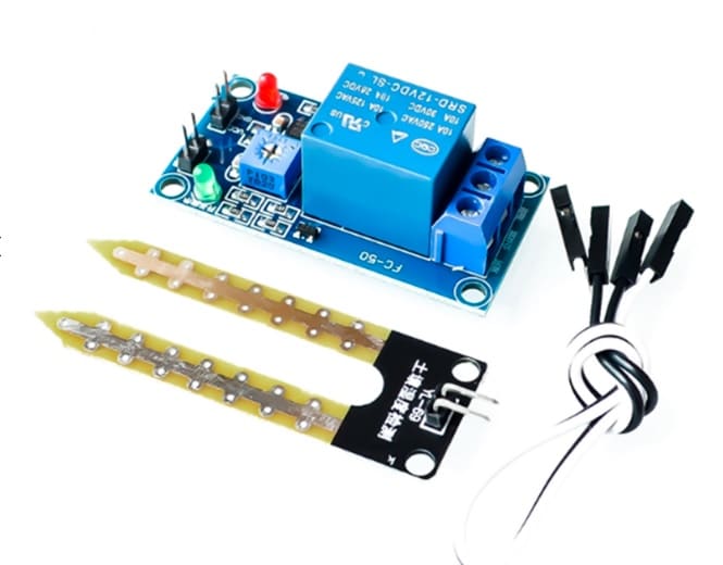
5V 12V Soil Moisture Sensor Relay Control Module
Pair with the FC-37 rain sensor for a complete outdoor irrigation system — soil sensor controls watering, rain sensor prevents it during rainfall.
Reading Digital Output: Rain / No Rain Detection
The digital output is the simplest way to use the FC-37 — it is either raining or it is not. This is perfect for triggering relays, sending alerts, or controlling simple actuators. Here is the basic sketch:
const int RAIN_DO_PIN = 7;     // Digital output from FC-37
const int BUZZER_PIN  = 8;     // Optional buzzer or relay pin
const int LED_PIN     = 13;    // Onboard LED

void setup() {
  pinMode(RAIN_DO_PIN, INPUT);
  pinMode(BUZZER_PIN,  OUTPUT);
  pinMode(LED_PIN,     OUTPUT);
  Serial.begin(9600);
}

void loop() {
  int rainState = digitalRead(RAIN_DO_PIN);

  // FC-37 digital output is ACTIVE LOW:
  // HIGH = dry (no rain), LOW = rain detected
  if (rainState == LOW) {
    Serial.println("Rain detected! Taking action...");
    digitalWrite(LED_PIN,    HIGH);  // Turn on LED
    digitalWrite(BUZZER_PIN, HIGH);  // Sound buzzer / trigger relay
  } else {
    Serial.println("No rain. All clear.");
    digitalWrite(LED_PIN,    LOW);
    digitalWrite(BUZZER_PIN, LOW);
  }

  delay(500);
}
Active LOW logic: The digital output of the FC-37 is inverted — LOW means wet (rain detected). This is because the LM393 comparator output pulls LOW when its non-inverting input (sensing voltage) drops below the reference voltage set by the potentiometer. Keep this in mind to avoid logic errors.
Reading Analog Output: Rainfall Intensity Measurement
The analog output gives you a continuous 0–5V signal proportional to the water coverage on the sensing board. The Arduino ADC converts this to 0–1023. Here is the important inversion: more water = lower analog value. A dry board reads close to 1023 (high voltage); a fully wet board reads close to 0 (low voltage, low resistance path to GND).
const int RAIN_AO_PIN = A0;

void setup() {
  Serial.begin(9600);
}

void loop() {
  int rawValue = analogRead(RAIN_AO_PIN);

  // Invert so higher value = more rain (more intuitive)
  int rainIntensity = 1023 - rawValue;

  // Map to percentage (0% = dry, 100% = fully wet)
  int rainPercent = map(rainIntensity, 0, 1023, 0, 100);

  // Classify intensity
  String condition;
  if (rawValue > 900) {
    condition = "Dry";
  } else if (rawValue > 700) {
    condition = "Light drizzle";
  } else if (rawValue > 400) {
    condition = "Moderate rain";
  } else {
    condition = "Heavy rain";
  }

  Serial.print("Raw ADC: "); Serial.print(rawValue);
  Serial.print("  |  Rain %: "); Serial.print(rainPercent);
  Serial.print("%  |  Condition: "); Serial.println(condition);

  delay(1000);
}
The threshold values (900, 700, 400) are approximate and vary between individual sensor boards. Calibrate them to your specific sensor by manually dripping controlled amounts of water on the sensing board and recording the corresponding ADC values.
Setting the Sensitivity Threshold
The blue potentiometer on the control board is the key to getting reliable digital output. Here is how to set it correctly:
- Connect the FC-37 to your Arduino and power it up
- Open the Serial Monitor and run the analog reading sketch to monitor raw values
- Observe the raw value on a completely dry board (should be 900–1023)
- Drip a small amount of water (1–2 drops) on the sensing board
- Observe the new raw value (might be 700–850 for a light drizzle)
- Turn the potentiometer with a small screwdriver. Clockwise raises the comparator reference voltage (triggers digital output with less water). Counterclockwise lowers it (requires more water to trigger).
- Adjust until the green LED (on the control board) turns ON at exactly the water level you want to detect as “rain”
For most applications, setting the threshold to trigger on a light drizzle is appropriate — you want early warning before heavy rain arrives. Set it too sensitive and morning dew or fog may trigger false positives.
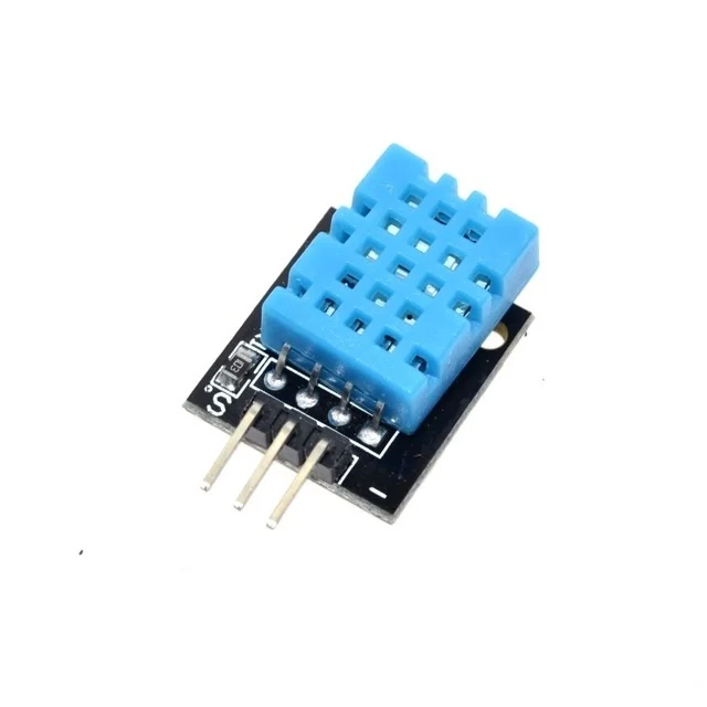
DHT11 Digital Relative Humidity and Temperature Sensor Module
Add humidity and temperature data to your weather station alongside the FC-37 rain sensor for complete environmental monitoring.
Practical Projects Using the FC-37
1. Smart Irrigation Controller
Combine the FC-37 with a soil moisture sensor and a relay-controlled pump. The logic: if soil is dry AND it is NOT raining → water the plants. If it IS raining → skip watering (no point watering in the rain). This is one of the most popular and practical FC-37 applications in India’s variable monsoon climate.
// Simplified irrigation logic
bool isRaining = (digitalRead(RAIN_DO_PIN) == LOW);
bool soilDry   = (analogRead(SOIL_PIN) > SOIL_DRY_THRESHOLD);

if (soilDry && !isRaining) {
  digitalWrite(PUMP_RELAY, HIGH);  // Water the plants
} else {
  digitalWrite(PUMP_RELAY, LOW);   // Skip watering
}
2. Automatic Window/Skylight Closer
Connect the DO output to a relay that controls a motorized window or skylight actuator. When rain is detected, the relay closes, triggering the motor to close the window. Add a manual override button for user control.
3. Vehicle Wiper Automation
In DIY RC cars or educational vehicle projects, mount the FC-37 horizontally and use the analog output to modulate wiper speed — light rain gets slow wipers, heavy rain gets fast wipers. A classic automotive engineering demonstration project.
4. Weather Station Dashboard
Log FC-37 analog readings every minute to an SD card or send them to Thingspeak/Firebase over WiFi (with ESP8266/ESP32). Combined with a DHT22 (temperature/humidity), BMP280 (pressure/altitude), and a wind speed sensor, you have a complete personal weather station.
5. Basement Flood Alert
Place the sensing board flat on the basement floor. Any water intrusion (not necessarily rain) will trigger the alert. Connect to a buzzer and an SMS notification module (SIM800L or similar) for remote alerts when you are away from home.
Extending Sensor Longevity: Corrosion Prevention
The biggest weakness of the FC-37 is that it is continuously powered — current flows through the nickel-plated tracks whenever the sensor is wet, causing electrolytic corrosion that gradually degrades the tracks over months of outdoor use. Here are the most effective countermeasures:
Power the Sensor Only When Needed
Connect the FC-37’s VCC through a digital Arduino output pin (instead of directly to 5V). Power the sensor only when taking a reading, then power it off. This dramatically extends sensor life:
const int RAIN_VCC_PIN = 6;  // Digital pin powers the sensor
const int RAIN_AO_PIN  = A0;

void readRainSensor() {
  digitalWrite(RAIN_VCC_PIN, HIGH);  // Power on
  delay(10);                         // Settle time
  int reading = analogRead(RAIN_AO_PIN);
  digitalWrite(RAIN_VCC_PIN, LOW);   // Power off
  return reading;
}
Important: Digital output pins on Arduino Uno can supply up to 40mA, which is sufficient for the FC-37 module.
Coat Tracks with Conformal Coating
After deployment, apply a thin layer of acrylic conformal coating spray (widely available at electronics stores) to the BACK side of the sensing board — not the track side. This protects solder joints and component leads without affecting sensing performance.
Replace at Season’s End
FC-37 sensing boards cost ₹30–50 each. Many makers simply accept that the sensing board is a consumable and replace it annually. Keep spare sensing boards on hand.
Frequently Asked Questions
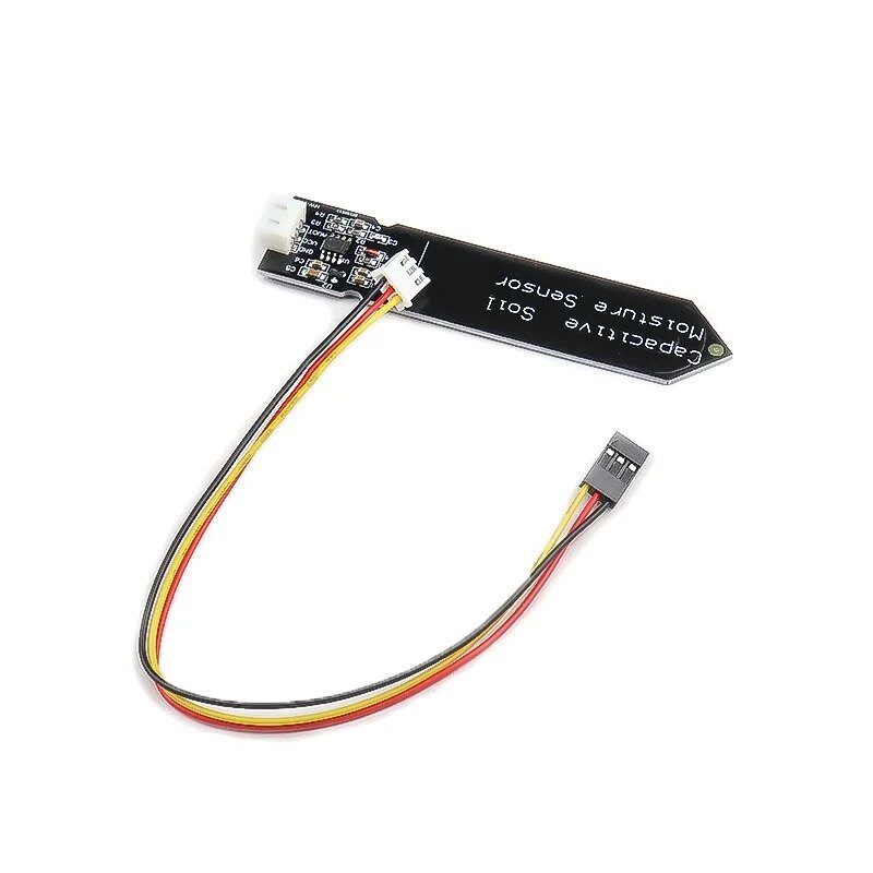
Capacitive Soil Moisture Sensor
Corrosion-resistant capacitive design — the ideal companion to your FC-37 rain sensor for a complete smart irrigation system.
Conclusion
The FC-37 rain sensor is one of the most accessible and practically useful sensors for Arduino beginners and intermediate makers alike. With a simple 4-wire connection, no additional components (the LM393 comparator is built in), and both digital and analog outputs, it slots effortlessly into a wide variety of projects. Understanding the active-LOW digital logic, calibrating the potentiometer threshold, and implementing pulsed power for longevity are the three skills that separate a reliable outdoor rain detection system from one that fails after a month.
Whether you are building an automated greenhouse, protecting outdoor electronics, or adding rainfall data to your weather station, the FC-37 gives you a solid, low-cost foundation. And combining it with a soil moisture sensor and a relay creates a genuinely useful smart irrigation system that pays for itself in saved water and healthier plants within a single growing season.


Add comment