
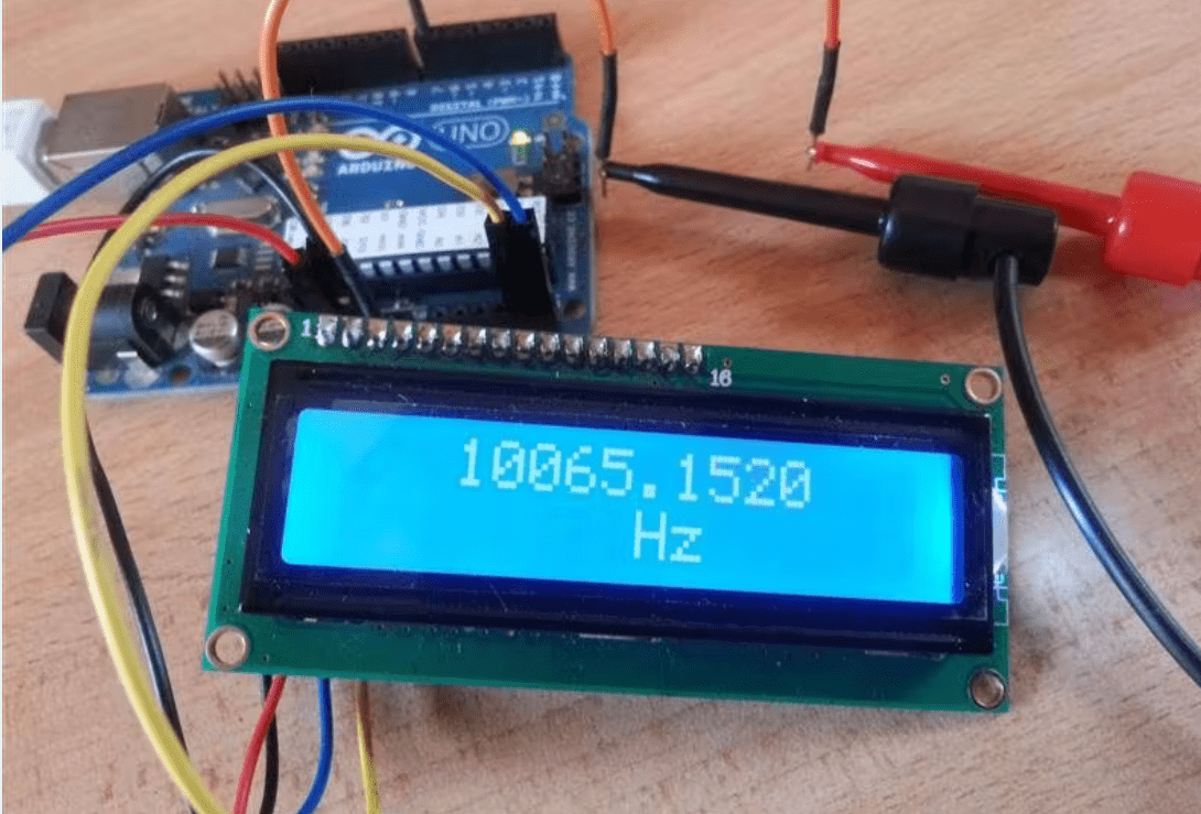
Arduino Frequency Counter Kit with 16×2 LCD Display
Frequency Counter, as the name indicates, is an electronic device or component, which is used to measure the frequency of a signal. In case of a repetitive electronic signal, a frequency counter measures the number of pulses in that signal.
We generally use an oscilloscope to depict the signal, calculate the time period of the signal and finally convert it to calculate the frequency of the signal. But, oscilloscopes are very expensive and everyone cannot afford it.
Hence, a simple Digital Frequency Counter can be built which might come in handy to measure the frequency of a clock signal, for example.
In this project, an Arduino based Digital Frequency Counter is designed to measure the frequency of an incoming signal.
Circuit Diagram: –
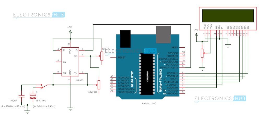
Arduino Frequency Counter Circuit Diagram
Components
Arduino Part
(AI0001) Arduino UNO
(AI0006) 16 X 2 LCD Display
(AI0046) Prototyping Board
(AI0380) Connecting wire
Signal Generator Part
(AI0173) NE555 Timer IC
(AI0174) 10 KΩ Potentiometer x 1
(AI0869) 100 nF Capacitor (Code: 104)
(AI0868) 1 µF / 16V Electrolytic Capacitor
(AI0082) 5V Power Supply (12V is not suitable as it might damage Arduino board).
Circuit Design
The design of the Frequency Counter using Arduino UNO can be divided in to two parts: The Arduino part, where the processing of the signal’s information takes place and the Signal Generator part, where the signal whose frequency to be measured is generated.
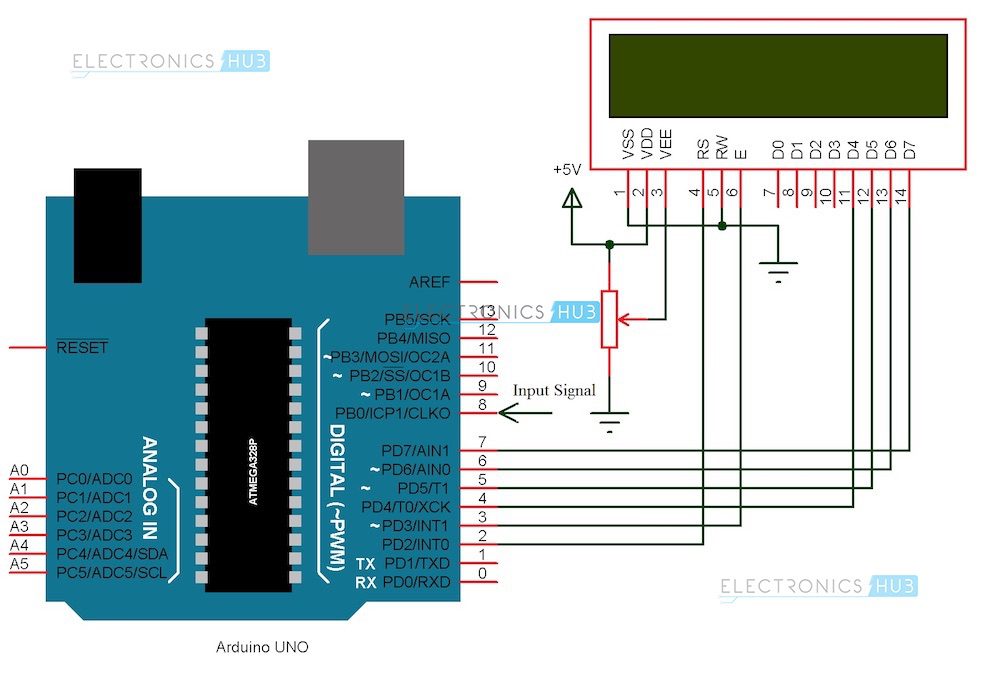
Arduino Circuit
Arduino part of the project consists of Arduino UNO board and a 16 X 2 LCD Display. Pins 1 and 2 of the LCD (Vss and Vdd) are connected to ground and 5V supply respectively. Pin 3 (Vee), which is used to adjust the contrast of the display, is connected a Potentiometer.
Pins 4 and 6 (RS and E) of the LCD are connected to digital I/O Pins 2 and 3 of the Arduino. Pin 5 (RW) of the LCD is connected to ground.
Pins 11 to 14 (D4 to D7) i.e. the data pins of the LCD are connected to the digital I/O pins 4 to 7 of Arduino. Pins 15 and 16 of the LCD are supply pins of the backlight LEDs and are connected to ground and 5V (Pin 16 to 5V through a 1KΩ resistor) respectively.
Features
6 characters wide, 2 rows
White text on the yellow background
Single LED backlight included can be dimmed easily with a resistor or PWM.
Can be fully controlled with only 6 digital lines! (Any analog/digital pins can be used)
Specification
| Model | JHD 16×2 |
|---|---|
| Characters | 16 |
| Character Color | White |
| Backlight | Blue |
| Input Voltage (V) | 5 |
| Length (mm): | 80 |
| Width (mm): | 36 |
| Height (mm): | 14.5 |
| Weight (g): | 30 |
Applications
A simple frequency counter, using simple components is designed that can be used to measure the frequency of a pulse without the need of an oscilloscope.
Multiple ranges of frequencies can be measured by selecting suitable components.
Frequencies of all types of test signals can be calculated by adding a Schmitt Trigger between the generated signal and Arduino.
Arduino Frequency Counter Kit with 16×2 LCD Display Overview
The Arduino Frequency Counter Kit with 16×2 LCD Display (Model GM1602A) is a compact, Arduino-based instrument designed to measure the frequency of repetitive electronic signals. Its built-in 16×2 alphanumeric LCD provides real-time pulse count readouts, making it ideal for hobbyists, students, and electronics technicians.
Key Features of Arduino Frequency Counter Kit with 16×2 LCD Display
- 16×2 LCD module (1602 resolution) for clear frequency display
- Arduino-based design with 16 I/O pins for easy interfacing
- Operating temperature range from –20 °C to 70 °C for versatile use
- Model GM1602A PCB assembly for reliable signal measurement
- Accurate pulse counting for clock signals and square waves
- Genuine product, fast shipping from Zbotic within 24 hours
Applications and Use Cases
- Measuring clock frequencies in microcontroller and FPGA projects
- Verifying output of signal generators and oscillators
- Testing RF modules and simple radio circuits
- Educational labs for teaching digital electronics and timing
- Calibration checks for DIY waveform and function generators
How to Use Arduino Frequency Counter Kit with 16×2 LCD Display
Assemble the kit components onto the provided PCB, then connect a 5 V DC power supply to the VCC and GND terminals. Feed your input signal into the designated frequency input pin, and the onboard Arduino-compatible microcontroller will count pulses and update the 16×2 LCD in real time. No additional modules are required—simply power up and observe the display.
Why Buy from Zbotic?
- Genuine Products: All items sourced from authorized distributors
- Fast Shipping: Orders ship within 24 hours with tracking (non backordered products)
- Free Shipping: Free delivery on qualifying orders
- COD Available: Cash on Delivery, UPI, cards, net banking
- Technical Support: Expert help for setup and troubleshooting
- Easy Returns: Hassle-free replacement for defective products
Frequently Asked Questions
What frequency range does this counter support?
The kit measures repetitive signals from approximately 1 Hz up to around 100 kHz, depending on signal amplitude and waveform stability.
Is an external Arduino board required?
No external board is needed. The kit includes an onboard Arduino-compatible microcontroller and the 16×2 LCD module for standalone operation.
How can I calibrate the frequency readings?
You can fine-tune readings by adjusting the onboard trimmer potentiometer or modifying the calibration constant in the Arduino sketch and re-uploading it via the Arduino IDE.
Technical Specifications
| Brand | Arduino |
|---|---|
| Package Quantity | 2 pcs |
| SKU | DIY020 |
| Weight | 0.30 kg |
| Availability | Out of Stock |
Applications & Use Cases
The Arduino Frequency Counter Kit with 16×2 LCD Display is a versatile digital voltage, current and frequency meter used across a wide range of applications including electronics projects, DIY builds, prototyping, and educational experiments.
Common use cases:
- Integrating into a custom electronics project
- Learning and experimenting with circuits
- Replacing or upgrading components in existing setups
This product is ideal for electronics enthusiasts, engineers, and students.
Technical Tip: Always verify voltage and current requirements before connecting to your circuit. Check datasheets for detailed specifications and pin configurations.
Shipping & Delivery
- Free shipping on orders above ₹999 across India
- Dispatched within 1-3 business days
- Expected delivery: 3-7 business days depending on location
- Secure packaging to ensure safe transit of electronic components
- Genuine Arduino product sourced from authorized channels


Sarthak Luthra –
Good Arduino Frequency Counter Kit with 16×2. Works well with Arduino IDE. Headers could be soldered more neatly.
Paras Bhat –
Good Arduino Frequency Counter Kit with 16×2. Took a while to get the drivers working but board itself is solid.
Pooja Pandey (verified owner) –
Fantastic Arduino Frequency Counter Kit with 16×2! All GPIO pins tested and working. Great for prototyping.
Abhishek Kohli (verified owner) –
Excellent Arduino Frequency Counter Kit with 16×2! Perfect for my Arduino project. All pins working correctly.
Mukesh Gupta (verified owner) –
Superb Arduino Frequency Counter Kit with 16×2! Compatible with all my existing Arduino shields and libraries.
Rishabh Kumar (verified owner) –
Outstanding quality Arduino Frequency Counter Kit with 16×2. I teach electronics and order these in bulk for my classes.
Meera Negi (verified owner) –
Very satisfied with this Arduino Frequency Counter Kit with 16×2. Fast shipping and genuine components. Zbotic is the best!
Shivam Bhandari (verified owner) –
Very satisfied with this Arduino Frequency Counter Kit with 16×2. Fast shipping and genuine components. Zbotic is the best!
Gauri Gill (verified owner) –
This Arduino Frequency Counter Kit with 16×2 is genuine quality. My students love working with it in our robotics lab.
Kritika Negi (verified owner) –
Outstanding quality Arduino Frequency Counter Kit with 16×2. I teach electronics and order these in bulk for my classes.
Himanshu Trivedi (verified owner) –
Superb Arduino Frequency Counter Kit with 16×2! Compatible with all my existing Arduino shields and libraries.
Raj Rathore –
This Arduino Frequency Counter Kit with 16×2 is genuine quality. My students love working with it in our robotics lab.
Aditi Mishra –
Good Arduino Frequency Counter Kit with 16×2. Took a while to get the drivers working but board itself is solid.
Sandeep Grewal –
Very satisfied with this Arduino Frequency Counter Kit with 16×2. Fast shipping and genuine components. Zbotic is the best!
Himanshu Garg (verified owner) –
Outstanding quality Arduino Frequency Counter Kit with 16×2. I teach electronics and order these in bulk for my classes.
Nikhil Iyer –
Using this Arduino Frequency Counter Kit with 16×2 for my smart farming project. Reliable and easy to interface.
Manish Pillai –
Bought multiple units of this Arduino Frequency Counter Kit with 16×2. All working great. Best store for Arduino components.
Ojas Solanki (verified owner) –
Bought multiple units of this Arduino Frequency Counter Kit with 16×2. All working great. Best store for Arduino components.
Piyush Das (verified owner) –
Superb Arduino Frequency Counter Kit with 16×2! Compatible with all my existing Arduino shields and libraries.
Urmi Arora (verified owner) –
Love this Arduino Frequency Counter Kit with 16×2. Using it for my home automation project, very reliable.
Priya Reddy (verified owner) –
Using this Arduino Frequency Counter Kit with 16×2 for my smart farming project. Reliable and easy to interface.
Anirudh Gill (verified owner) –
Love this Arduino Frequency Counter Kit with 16×2. Using it for my home automation project, very reliable.
Shubham Thakur (verified owner) –
Excellent Arduino Frequency Counter Kit with 16×2! Built a weather station with this. Everything works as expected.
Hitesh Hegde (verified owner) –
This Arduino Frequency Counter Kit with 16×2 is genuine quality. My students love working with it in our robotics lab.