
OneWire Protocol: DS18B20 Sensor Bus with Multiple Sensors
One of the most elegant features in embedded electronics is the ability to connect dozens of sensors using just a single wire. The OneWire protocol DS18B20 multiple sensors combination is a maker’s best friend — you can read temperatures from 10, 20, or even 64 sensors scattered across a building, a greenhouse, or a server rack, all connected in parallel on a single GPIO pin. This tutorial covers the OneWire protocol in depth and shows you exactly how to wire and code a multi-sensor system on Arduino that works reliably in Indian ambient conditions.
How the OneWire Protocol Works
The 1-Wire (OneWire) protocol was developed by Dallas Semiconductor (now Maxim Integrated) in the 1990s. It is a serial communication protocol that uses a single bidirectional data line for both transmitting commands and receiving data — combined with a shared ground. The bus can even optionally power the devices through the data line itself (parasite power mode).
The protocol works through a master-slave architecture:
- Master (Arduino): Initiates all communication, issues reset pulses, and addresses specific slaves.
- Slaves (DS18B20 sensors): Each has a unique 64-bit ROM address (burned at the factory). They respond only when addressed by the master.
The electrical signalling uses low-speed (15.4 kbps standard / 125 kbps overdrive) open-drain logic. The master pulls the line LOW to communicate, and a pull-up resistor (typically 4.7 kΩ) holds the line HIGH at idle. All devices share this single wire — this is what makes 1-Wire so useful for distributed sensor networks where running multiple wires would be impractical.
The DS18B20 temperature sensor measures from -55°C to +125°C with ±0.5°C accuracy from -10°C to +85°C, and communicates exclusively over the 1-Wire bus. It converts temperature in 9-bit to 12-bit resolution, with a 12-bit conversion taking 750 ms maximum. For most Indian IoT applications (ambient temperature monitoring, server room monitoring, aquarium temperature), 12-bit resolution (0.0625°C steps) is more than adequate.
DS18B20 Unique Address System
Every DS18B20 manufactured has a unique 64-bit ROM code laser-programmed at the factory. This code is structured as:
- Byte 0: Family code (0x28 for DS18B20)
- Bytes 1–6: Unique serial number (48 bits — over 281 trillion unique combinations)
- Byte 7: CRC8 checksum for error detection
This addressing scheme is what allows multiple sensors to share one wire. The master can broadcast to all sensors simultaneously (using the Skip ROM command) or address individual sensors by their unique 64-bit address. When you add a new sensor, your code must first scan the bus to discover its address, then store it for future use.
Wiring: Normal vs Parasite Power Mode
The DS18B20 supports two power modes:
Normal (External) Power Mode — Recommended
Three connections per sensor: VDD (3.3V or 5V), GND, and DQ (data). All DQ pins connect together on a single wire to one Arduino GPIO pin. A single 4.7 kΩ pull-up resistor from DQ to VDD is shared by the entire bus. This is the most reliable mode and is required when you have more than 2–3 sensors or when sensors are far from the Arduino.
Parasite Power Mode
Two connections per sensor: GND and DQ (data). The sensor steals power from the data line during logic-HIGH periods. VDD is tied to GND. This simplifies cabling but has significant limitations: maximum 3 sensors on one bus, limited cable length, and cannot perform simultaneous temperature conversion on multiple sensors. Avoid parasite mode for multi-sensor builds.
| Feature | Normal Power | Parasite Power |
|---|---|---|
| Wires per sensor | 3 (VCC, GND, DQ) | 2 (GND, DQ) |
| Max sensors on bus | Up to 127+ | 2–3 (unreliable with more) |
| Max cable length | 300m+ (with boosted pull-up) | ~5m |
| Simultaneous conversion | Yes | No |
Wiring Multiple DS18B20 Sensors
For a bus with multiple sensors:
- Connect all DS18B20 VDD pins to Arduino 5V (or a separate 5V rail for long cable runs).
- Connect all DS18B20 GND pins to Arduino GND (one shared ground wire).
- Connect all DS18B20 DQ pins together — this forms the 1-Wire data bus.
- Connect the data bus to Arduino pin 2 (or any digital GPIO).
- Add a single 4.7 kΩ resistor from the data bus to 5V. You need exactly one resistor for the entire bus, not one per sensor.
For long cable runs (>10 metres, common in greenhouse or industrial applications), reduce the pull-up to 2.2 kΩ or use an active pull-up circuit. Keep cable capacitance in mind — use Cat5e data cable (twisted pair) rather than flat ribbon cable for runs over 5 metres.
Important for Indian conditions: If sensors are exposed to outdoor temperatures (40°C+ summers, 5°C winters in north India), use the waterproof DS18B20 probe version (with stainless steel tip and 1 metre cable). Standard TO-92 package DS18B20s are only suitable for PCB or enclosure use.

0.96 Inch I2C IIC OLED LCD Module 4pin (with GND VCC) White SSD1306 Chip
Display all your DS18B20 readings on this compact I2C OLED — scroll through sensor addresses and temperatures in real time on a 4-wire display.
Arduino Code: Reading a Single DS18B20
First, install two libraries in the Arduino IDE: OneWire and DallasTemperature. Both are available in the Library Manager (Sketch → Include Library → Manage Libraries).
#include <OneWire.h>
#include <DallasTemperature.h>

#define ONE_WIRE_BUS 2  // Data wire to Arduino pin 2

OneWire          oneWire(ONE_WIRE_BUS);
DallasTemperature sensors(&oneWire);

void setup() {
  Serial.begin(9600);
  sensors.begin();
  Serial.print("Found ");
  Serial.print(sensors.getDeviceCount());
  Serial.println(" DS18B20 sensor(s)");
}

void loop() {
  sensors.requestTemperatures(); // broadcast conversion to all sensors
  float tempC = sensors.getTempCByIndex(0); // first sensor (index 0)
  Serial.print("Temperature: ");
  Serial.print(tempC);
  Serial.println(" °C");
  delay(1000);
}
Upload this, open Serial Monitor at 9600 baud. You should see the temperature reading and the count of detected sensors. If count shows 0, check your pull-up resistor and wiring connections.
Arduino Code: Reading All Sensors Automatically
The real power of OneWire is reading all sensors without hardcoding addresses. The DallasTemperature library scans the bus and enumerates each sensor by index:
#include <OneWire.h>
#include <DallasTemperature.h>

#define ONE_WIRE_BUS 2

OneWire          oneWire(ONE_WIRE_BUS);
DallasTemperature sensors(&oneWire);

int deviceCount = 0;
DeviceAddress deviceAddresses[10]; // store up to 10 addresses

void printAddress(DeviceAddress addr) {
  for (uint8_t i = 0; i < 8; i++) {
    if (addr[i] < 16) Serial.print("0");
    Serial.print(addr[i], HEX);
  }
}

void setup() {
  Serial.begin(9600);
  sensors.begin();
  deviceCount = sensors.getDeviceCount();
  Serial.print("Found ");
  Serial.print(deviceCount);
  Serial.println(" sensor(s):");

  for (int i = 0; i < deviceCount; i++) {
    sensors.getAddress(deviceAddresses[i], i);
    Serial.print("  Sensor ");
    Serial.print(i);
    Serial.print(" address: ");
    printAddress(deviceAddresses[i]);
    Serial.println();
  }
  // Set resolution to 12-bit for all sensors
  sensors.setResolution(12);
}

void loop() {
  sensors.requestTemperatures(); // send conversion command to all
  // requestTemperatures blocks for 750ms (12-bit conversion time)

  Serial.println("--- Temperature readings ---");
  for (int i = 0; i < deviceCount; i++) {
    float tempC = sensors.getTempC(deviceAddresses[i]);
    Serial.print("Sensor ");
    Serial.print(i);
    Serial.print(" (");
    printAddress(deviceAddresses[i]);
    Serial.print("): ");

    if (tempC == DEVICE_DISCONNECTED_C) {
      Serial.println("ERROR - sensor disconnected!");
    } else {
      Serial.print(tempC);
      Serial.println(" °C");
    }
  }
  Serial.println();
  delay(2000);
}
This code auto-discovers all sensors on boot, prints their unique hex addresses, then reads all temperatures every 2 seconds. The DEVICE_DISCONNECTED_C check detects when a sensor is removed or has a wiring fault — critical for production systems.
Non-blocking conversion: For time-sensitive applications (like ESP32 IoT nodes that also handle WiFi), avoid the blocking requestTemperatures(). Instead, call sensors.setWaitForConversion(false) and sensors.requestTemperatures(), wait 750 ms in your own code, then call sensors.getTempC(). This allows other tasks to run during the conversion.
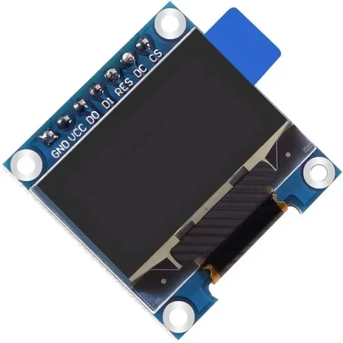
0.96 Inch SPI OLED LCD Module + CSpin 7pin (with GND VCC) White SSD1306 Chip
SPI OLED for fast-refresh temperature dashboards — display all sensor readings with smooth scrolling in your DS18B20 multi-sensor project.
Displaying Readings on OLED
Combining the DS18B20 bus with a 0.96″ SSD1306 OLED display creates a self-contained temperature monitor. The I2C OLED uses only pins A4 (SDA) and A5 (SCL) on the Arduino, leaving the data bus pin free. Here is how to cycle through all sensor readings on the display:
#include <Adafruit_SSD1306.h>
// ... (include OneWire + DallasTemperature as before)

Adafruit_SSD1306 display(128, 64, &Wire, -1);

void setup() {
  // ... sensors.begin() as before ...
  display.begin(SSD1306_SWITCHCAPVCC, 0x3C);
  display.clearDisplay();
  display.setTextColor(SSD1306_WHITE);
}

void displayReadings() {
  sensors.requestTemperatures();
  display.clearDisplay();
  display.setTextSize(1);
  display.setCursor(0, 0);
  display.println("DS18B20 Multi-Sensor");
  display.drawLine(0, 10, 128, 10, SSD1306_WHITE);

  int yPos = 14;
  for (int i = 0; i < min(deviceCount, 5); i++) { // show up to 5
    float t = sensors.getTempC(deviceAddresses[i]);
    display.setCursor(0, yPos);
    display.print("S"); display.print(i + 1); display.print(": ");
    if (t == DEVICE_DISCONNECTED_C) {
      display.print("ERR");
    } else {
      display.print(t, 1); display.print((char)247); display.print("C");
    }
    yPos += 10;
  }
  display.display();
}

void loop() {
  displayReadings();
  delay(2000);
}
The OLED shows up to 5 sensors simultaneously at 10px line height on a 64px tall display. For more sensors, implement a scrolling display that cycles through pages of readings.
Practical Applications in India
Here are high-value use cases for DS18B20 multi-sensor systems specifically relevant to Indian makers and businesses:
Server room / UPS room monitoring: Place DS18B20 probes at intake and exhaust of server racks. Alert via SMS (using a GSM module) if temperature exceeds 28°C. Indian data centres routinely face cooling failures during summer power fluctuations.
Greenhouse / polyhouse temperature mapping: A single Arduino with 8–10 DS18B20 probes scattered across a greenhouse gives you a complete spatial temperature picture. Essential for growing strawberries or tomatoes in Indian hill stations where temperature varies significantly between floor and ceiling.
Aquarium monitoring: Indian tropical fish hobbyists use DS18B20 probes (waterproof version) inside fish tanks. Multiple sensors at different depths catch stratification issues in deep tanks.
Cold chain monitoring: For small food businesses (dairy, pharma distribution in India), a Raspberry Pi with OneWire DS18B20 probes inside refrigerators, combined with LoRa or GSM uplink, provides affordable cold chain monitoring that commercial solutions charge lakhs for.

1 Channel 12V 30A Relay Module with Optocoupler and Guide Rail
Add thermostat control to your DS18B20 build — trigger a relay to control a heater, cooler, or fan based on temperature thresholds read from the sensor bus.
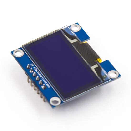
0.96 Inch SPI OLED LCD Module 6pin (with GND VCC) Blue SSD1306 Chip
Affordable blue OLED for sensor dashboards — great for server room or greenhouse displays showing live temperature from multiple DS18B20 probes.
Frequently Asked Questions
How many DS18B20 sensors can I connect to one Arduino pin?
The OneWire protocol theoretically supports 2^48 unique device addresses on a single bus — over 281 trillion. Practically, the limiting factor is bus capacitance: each metre of cable and each device adds capacitance that slows signal edges. With standard 4.7 kΩ pull-up and short cables (under 5m total), 10–20 sensors work reliably. For longer buses or more sensors, reduce the pull-up resistor to 2.2 kΩ or use a 1-Wire bus controller IC.
What is the difference between DS18B20 and DS18S20?
The DS18S20 is an older, fixed 9-bit (0.5°C resolution) version. The DS18B20 is the improved version with selectable 9/10/11/12-bit resolution. For Indian electronics stores and most online purchases, you will almost always receive the DS18B20. The family code distinguishes them: DS18B20 = 0x28, DS18S20 = 0x10.
My sensors all read -127°C. What is wrong?
-127°C (or -127.00 in DallasTemperature) is returned when the sensor cannot be reached on the bus. Common causes: (1) Missing or wrong pull-up resistor — must be 4.7 kΩ between DQ and VCC. (2) GND not shared between Arduino and sensors. (3) Correct power mode — if VDD pin is left floating and you’re not using parasite mode, the sensor won’t work. (4) Defective sensor — rarely, but it happens with budget sensors from unreliable suppliers.
Can I use DS18B20 with ESP32 or ESP8266 instead of Arduino?
Yes. Both the OneWire and DallasTemperature libraries are compatible with ESP8266 and ESP32. On ESP32, use any GPIO pin except GPIO6–11 (connected to internal flash). On ESP8266, avoid GPIO0, GPIO2, GPIO15 for the data bus as these have boot-mode implications. The 3.3V logic on ESP32/ESP8266 is fully compatible with DS18B20’s data line — use the same 4.7 kΩ pull-up to 3.3V.
How do I permanently label sensors so I know which is which in my room/greenhouse?
Read and print the 64-bit address of each sensor at startup (as shown in the code above). Write down the address printed on Serial Monitor and physically label the sensor wire with that last 2–3 bytes of the hex address using a permanent marker. Then in your final code, replace index-based reads with address-based reads using sensors.getTempC(deviceAddress) so sensor positions never swap even if you add or remove sensors from the bus.
Get Your Sensors and Displays from Zbotic
Build reliable temperature monitoring systems with quality components from Zbotic — OLED displays, relay modules, and communication hardware shipped fast across India.


Add comment