
The NEMA 23 stepper motor is the backbone of desktop CNC machines, laser cutters, plasma tables, and larger 3D printers. Its 57 mm square frame provides significantly more torque than the NEMA 17 motors found in standard FDM printers, making it the go-to choice when cutting forces, heavier gantries, or longer travel distances demand more muscle from the motion system.
This comprehensive guide covers everything you need to know about the NEMA 23: frame dimensions and torque specifications, bipolar wiring diagrams, microstepping driver selection, CNC axis setup calculations, and complete control code for both Arduino and GRBL-based systems. Whether you are designing a CNC router from scratch or upgrading an existing machine, this guide gives you the engineering foundation to do it right.
1. NEMA Frame Standard Explained
NEMA (National Electrical Manufacturers Association) motor frame sizes define the faceplate mounting dimensions, not the motor’s length or torque. The number following “NEMA” indicates the faceplate size in tenths of an inch:
- NEMA 8: 20.3 mm frame — micro-robotics, pen plotters
- NEMA 11: 28.2 mm frame — small 3D printers, camera sliders
- NEMA 17: 42.3 mm frame — standard 3D printers, small CNC
- NEMA 23: 57.2 mm frame — desktop CNC routers, laser cutters, medium gantries
- NEMA 34: 86.4 mm frame — industrial CNC, large format machines
The NEMA standard specifies mounting hole spacing (47.14 mm on NEMA 23), shaft diameter (typically 6.35 mm or 8 mm on NEMA 23), and overall faceplate size. Motor body length, winding resistance, and torque vary by manufacturer and model. This means NEMA 23 motors from different suppliers are mechanically interchangeable on the same machine but electrically different — always check winding specifications.
2. NEMA 23 Specifications
There is no single set of NEMA 23 specifications — torque and electrical properties vary widely by body length and winding design. Here are typical variants you will encounter:
| Variant | Body Length | Holding Torque | Phase Current | Phase Resistance |
|---|---|---|---|---|
| Short | 51 mm | 1.0–1.3 N·m | 1.5–2.0 A | 1.5–2.0 Ω |
| Standard | 76 mm | 1.8–2.2 N·m | 2.0–3.0 A | 0.9–1.5 Ω |
| Long | 112 mm | 2.8–3.0 N·m | 3.0–4.2 A | 0.5–1.0 Ω |
Common fixed parameters across most NEMA 23 steppers:
- Step angle: 1.8° per full step (200 steps per revolution)
- Steps per revolution: 200 (full step) — up to 3200 (1/16 microstep)
- Configuration: Bipolar (4-wire) or unipolar (6 or 8-wire)
- Shaft diameter: 6.35 mm (1/4″) or 8 mm — verify before coupling selection
- Mounting holes: M5 × 4 holes, 47.14 mm bolt circle
3. Understanding Torque Curves
The holding torque specification only applies at standstill with rated current flowing. As shaft speed increases, torque drops — this is the fundamental torque-speed curve of stepper motors. Understanding this curve prevents the most common NEMA 23 application failure: a machine that works perfectly at slow speed but loses steps and stalls at operating speed.
Three factors primarily affect where the torque curve drops off:
1. Supply voltage: Higher voltage allows current to rise faster in the inductance of the coils at high step rates. A 36 V supply maintains torque at far higher speeds than a 12 V supply on the same motor. For serious CNC applications, always run NEMA 23 motors at 24–48 V even if the coil voltage rating is lower — the current-limiting driver handles the actual current; higher supply voltage just improves high-speed torque.
2. Driver current limit: Set the driver’s current limit to the motor’s rated phase current (or up to 20% higher for brief periods). Too low a current limit reduces both holding torque and dynamic torque. Too high risks overheating the motor.
3. Step rate: Above a resonance frequency (typically 100–200 RPM for NEMA 23 steppers), torque begins dropping significantly. Mid-band resonance dampening (either electronic in modern drivers or mechanical via dampers) can recover some of this lost torque.
4. Wiring a Bipolar NEMA 23
Most NEMA 23 motors sold today are bipolar 4-wire motors. The four wires form two independent coils (phases):
- Coil A: Typically black + green (or red + blue, depending on manufacturer)
- Coil B: Typically red + blue (or yellow + white)
Identifying coil pairs: Use a multimeter in resistance mode. Two wires with ~0.5–2 Ω between them are the same coil. Two wires with infinite resistance are from different coils. Polarity within each coil can be reversed to change rotation direction — there is no wrong polarity, just two possible rotation directions.
Typical wiring to a stepper driver (e.g., DM542T):
NEMA 23 Motor          DM542T Driver
--------------         -----------
Black (A+)    →        A+
Green (A-)    →        A-
Red   (B+)    →        B+
Blue  (B-)    →        B-

Power Supply           DM542T
-----------            -------
+36V          →        VCC+
GND           →        VCC-

Arduino/Controller     DM542T
------------------     ------
D2 (STEP)     →        PUL+
GND           →        PUL-
D3 (DIR)      →        DIR+
GND           →        DIR-
D4 (ENABLE)   →        ENA+ (optional; float to always enable)
GND           →        ENA-
5. Choosing the Right Stepper Driver
NEMA 23 motors draw 1.5–4.2 A per phase depending on variant. Most beginner drivers cannot handle this:
| Driver | Max Current | Max Voltage | Suitable for NEMA 23? |
|---|---|---|---|
| A4988 | 2.0 A | 35 V | Only short variants (1.5–2.0 A), needs good cooling |
| DRV8825 | 2.5 A | 45 V | Marginal — adequate for 2 A motors with heatsink |
| TB6600 | 4.0 A | 42 V | Yes — good for 2–3.5 A NEMA 23 motors |
| DM542T | 4.2 A | 50 V | Yes — recommended for serious CNC builds |
| DM556 | 5.6 A | 50 V | Yes — for high-torque 4 A NEMA 23 motors |
For a reliable desktop CNC router with NEMA 23 motors, the TB6600 module or the DM542T industrial driver are the recommended choices. Avoid driving NEMA 23 with A4988 — the thermal stress on the driver reduces its lifespan significantly.

A4988 Stepper Motor Driver Controller Board (Red)
Popular A4988 microstepping driver — ideal for NEMA 17 and small NEMA 23 motors up to 2 A in 3D printers and light CNC builds.
6. Microstepping Explained
Full-step mode (200 steps/revolution) produces noticeable vibration and resonance. Microstepping divides each full step into smaller fractions by partially energising both coils simultaneously at intermediate current levels, creating intermediate rotor positions:
- Full step (1): 200 steps/rev, 1.8°/step — coarse, high torque, highest resonance
- Half step (2): 400 steps/rev, 0.9°/step — smoother, slightly reduced torque
- 1/4 step: 800 steps/rev, 0.45°/step
- 1/8 step: 1600 steps/rev, 0.225°/step — default for most 3D printers
- 1/16 step: 3200 steps/rev, 0.1125°/step — very smooth, used for high-resolution CNC
- 1/32 step: 6400 steps/rev — smooth but positional accuracy limited by mechanical compliance
Important: microstepping improves smoothness but does NOT improve positional accuracy proportionally. Mechanical compliance (flex in belts, leadscrew backlash) limits real accuracy to approximately full-step resolution regardless of microstepping setting. Microstepping’s main benefit is vibration reduction and quieter operation.
7. CNC Axis Setup Calculations
Setting up a CNC axis requires calculating the steps per millimetre — how many stepper pulses are needed to move the axis exactly 1 mm. This depends on three things: motor step resolution, drive mechanism, and microstepping setting.
Ball Screw or Leadscrew Axis
Steps/mm = (Motor Steps/Rev × Microstepping) / (Lead mm/Rev)

Example: NEMA 23, 1/8 microstepping, 5mm pitch leadscrew
Steps/mm = (200 × 8) / 5 = 320 steps/mm
Belt Drive Axis (GT2 Belt)
Pulley circumference = Teeth × 2mm (GT2 = 2mm pitch)

Example: 20-tooth GT2 pulley, 1/8 microstepping
Pulley circumference = 20 × 2 = 40mm
Steps/mm = (200 × 8) / 40 = 40 steps/mm
Rack and Pinion
Rack pitch circle: Module 1 = 1mm/tooth, Module 2 = 2mm/tooth
Pinion circumference = π × Module × Teeth

Example: Module 1, 20-tooth pinion, 1/8 microstepping
Circumference = π × 1 × 20 = 62.83mm
Steps/mm = (200 × 8) / 62.83 = 25.46 steps/mm
8. GRBL Configuration for NEMA 23
GRBL is the most widely used open-source CNC firmware for Arduino Uno/Nano. Key GRBL settings for NEMA 23 CNC axes (enter via serial terminal with $$ to read all settings):
$0=10     ; Step pulse time (microseconds) — keep at 10 for most drivers
$1=255    ; Step idle delay (milliseconds) — 255 = always keep motors energised
$2=0      ; Step port invert mask
$3=0      ; Direction port invert mask (flip if axis moves wrong direction)
$100=320  ; X steps/mm (adjust to your leadscrew/belt calculation)
$101=320  ; Y steps/mm
$102=320  ; Z steps/mm
$110=3000 ; X max feed rate (mm/min) — start conservative, increase after testing
$111=3000 ; Y max feed rate
$112=500  ; Z max feed rate (slower for Z axis)
$120=200  ; X acceleration (mm/sec²)
$121=200  ; Y acceleration
$122=100  ; Z acceleration
$130=400  ; X max travel (mm) — set to actual axis travel
$131=400  ; Y max travel
$132=100  ; Z max travel
After configuring, run a calibration test: command the axis to move exactly 100 mm, measure with a ruler, and adjust steps/mm accordingly: New steps/mm = (Current steps/mm × 100) / Actual distance travelled.
9. Arduino AccelStepper Code
For standalone NEMA 23 control without GRBL, the AccelStepper library provides acceleration, deceleration, and multi-axis synchronisation:
#include <AccelStepper.h>

// DRIVER interface mode (STEP + DIR pins)
#define STEP_PIN 2
#define DIR_PIN  3
#define EN_PIN   4

AccelStepper stepper(AccelStepper::DRIVER, STEP_PIN, DIR_PIN);

void setup() {
  pinMode(EN_PIN, OUTPUT);
  digitalWrite(EN_PIN, LOW);  // Enable driver (active LOW on most drivers)

  stepper.setMaxSpeed(2000.0);     // Steps per second
  stepper.setAcceleration(500.0);  // Steps per second squared

  Serial.begin(9600);
  Serial.println("NEMA 23 Ready");
}

void loop() {
  // Move 3200 steps forward (1 revolution at 1/16 microstepping)
  stepper.moveTo(3200);
  while (stepper.distanceToGo() != 0) {
    stepper.run();
  }
  delay(1000);

  // Move back to home
  stepper.moveTo(0);
  while (stepper.distanceToGo() != 0) {
    stepper.run();
  }
  delay(1000);
}
Multi-axis synchronised movement (e.g., CNC X and Y simultaneously):
#include <AccelStepper.h>
#include <MultiStepper.h>

AccelStepper stepperX(AccelStepper::DRIVER, 2, 3);
AccelStepper stepperY(AccelStepper::DRIVER, 5, 6);
MultiStepper steppers;

void setup() {
  stepperX.setMaxSpeed(2000);
  stepperY.setMaxSpeed(2000);
  steppers.addStepper(stepperX);
  steppers.addStepper(stepperY);
}

void loop() {
  long positions[2] = {6400, 3200}; // X: 2 revs, Y: 1 rev
  steppers.moveTo(positions);
  steppers.runSpeedToPosition();    // Blocks until done, syncs both axes

  long home[2] = {0, 0};
  steppers.moveTo(home);
  steppers.runSpeedToPosition();
}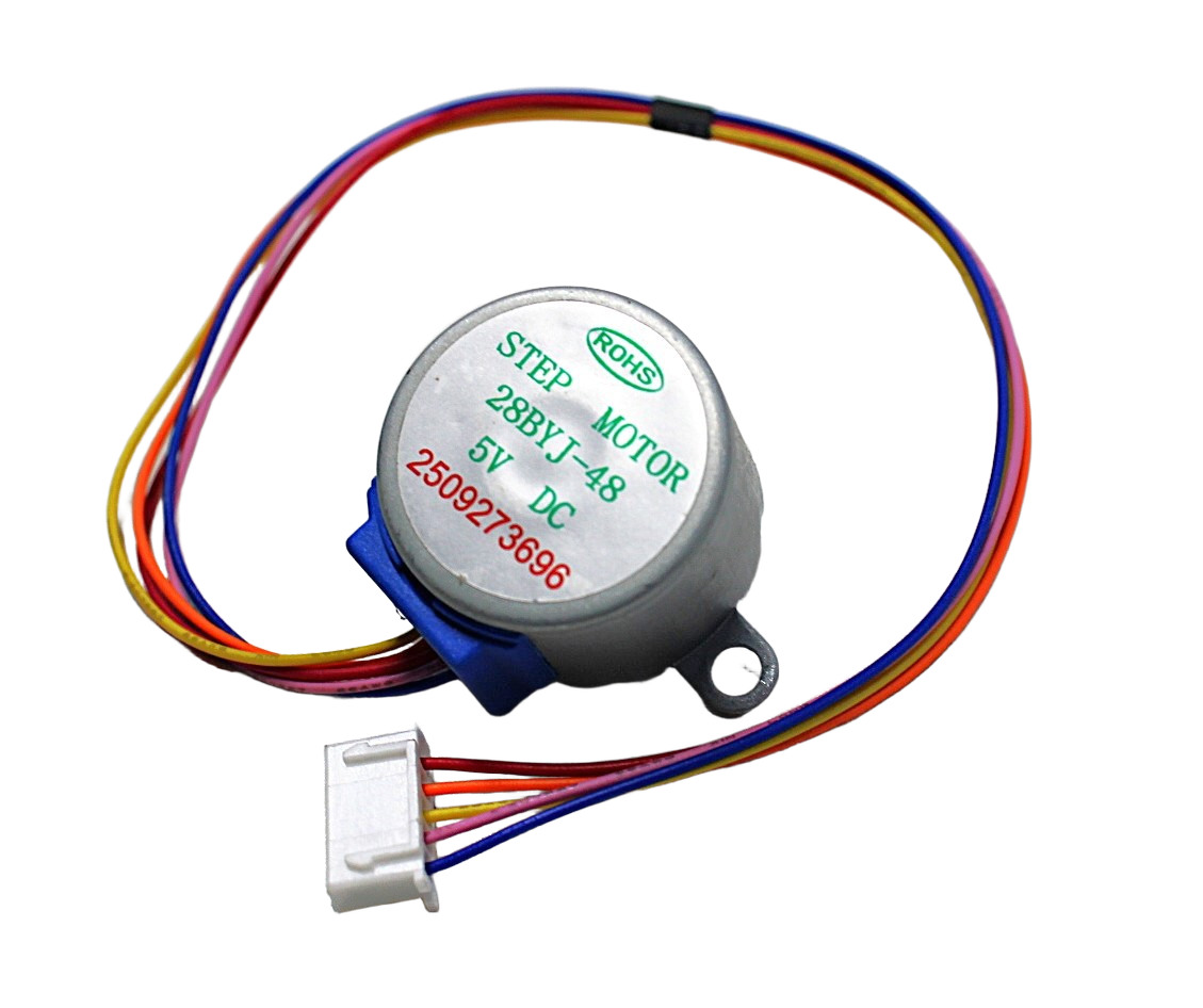
28BYJ-48 5V Stepper Motor
Entry-level unipolar stepper motor — ideal for learning AccelStepper code before upgrading to NEMA 23 hardware for CNC builds.
10. CNC Application Examples
10.1 Desktop CNC Wood Router
A 3-axis CNC router for cutting hardwood, plywood, and aluminium typically uses three NEMA 23 motors (X, Y, Z axes). X and Y axes use belt drive (20T GT2 pulley) for fast rapids; Z axis uses a 5 mm pitch leadscrew for precise depth control. Drivers: three TB6600 modules at 36 V supply. Control board: Arduino Uno with GRBL 1.1 shield. Feed rates: 3000 mm/min for wood, 800 mm/min for aluminium.
10.2 Laser Cutter (40–80W CO2)
CO2 laser cutters commonly use NEMA 23 on X and Y with high-speed belt drives (40T pulleys for faster travel). GRBL-based controllers (or dedicated laser controllers like Ruida) drive the steppers. Z axis (bed height) uses a NEMA 17 or NEMA 23 depending on bed weight.
10.3 Plasma Cutting Table
Plasma cutting requires rapid, precise axis movement over large travel distances (1m+). NEMA 23 long-body motors (2.8 N·m) with rack-and-pinion drives and DM542T drivers on 48 V supplies handle the long axis travel while maintaining adequate torque. GRBL-Plasma or Mach3/Mach4 provides THC (Torch Height Control) integration.
10.4 Large Format 3D Printer
Printers with build volumes above 300 mm × 300 mm benefit from NEMA 23 on the heavy gantry axes. The heavier NEMA 23 motor provides the torque needed for larger printhead masses and faster print speeds without losing steps. NEMA 17 remains appropriate for lighter extruder and small-format axes.

NEMA 17 5.6 kg-cm Stepper Motor with Detachable Cable
High-torque NEMA 17 with detachable cable and D-type shaft — an excellent step between 28BYJ-48 and NEMA 23 for medium-duty CNC and 3D printer axes.
Frequently Asked Questions
What power supply voltage should I use for NEMA 23 steppers?
24–48 V DC is the recommended range. Higher voltage significantly improves high-speed torque because it drives current through the coil inductance faster. A 36 V power supply is a good compromise — it roughly triples high-speed torque compared to 12 V while staying within most driver voltage ratings. Use a switching power supply rated 10–20% above maximum current demand.
Why does my NEMA 23 lose steps under load?
The three most common causes: (1) driver current limit set too low — increase to motor’s rated current; (2) supply voltage too low — upgrade to 36 V or 48 V; (3) acceleration too high — reduce $120/$121 GRBL values or lower AccelStepper acceleration. Test with very low acceleration first, then increase until steps are lost, then back off 20%.
Can I use NEMA 23 motors with a Raspberry Pi directly?
No. Raspberry Pi GPIO cannot generate the precise, fast step pulses needed for reliable stepper control — the Linux OS introduces jitter. Use a dedicated CNC control board (Arduino Uno with GRBL, or a dedicated controller like the CNC Shield). Raspberry Pi can send G-code to the controller via serial/USB.
What is the difference between a single-shaft and double-shaft NEMA 23?
Double-shaft motors have an exposed shaft at both ends of the motor body. This is useful for attaching a manual handwheel or encoder on the rear shaft for closed-loop position feedback, while the front shaft drives the CNC axis. Most hobby CNC builds use single-shaft motors.
How do I reduce vibration and noise from my NEMA 23?
Use 1/8 or 1/16 microstepping for smoother operation. Mount motors with rubber isolation gaskets between the motor face and the machine frame. Reduce motor current to the minimum that reliably holds position (typically 60–70% of rated current in idle). Some modern drivers (TMC2208, TMC5160) have StealthChop mode that dramatically reduces stepper noise.
Is NEMA 23 suitable for a 3D printer?
For standard FDM printers with 200–250 mm build area, NEMA 17 is the standard and NEMA 23 is overkill (heavier, more inertia). NEMA 23 becomes beneficial in large-format printers (300 mm+), delta printers with heavy effectors, or machines with long belt runs where the larger motor torque compensates for belt stretch and gantry weight.
Conclusion
The NEMA 23 stepper motor is a powerful, versatile actuator that enables desktop CNC machines, laser cutters, and large-format 3D printers to achieve the torque and precision that smaller motors cannot deliver. Understanding its torque curve, selecting the right driver and supply voltage, and correctly calculating steps per millimetre are the three pillars of a successful NEMA 23 implementation.
Start with a proper driver (TB6600 or DM542T), a 36–48 V power supply, and conservative acceleration settings — then iterate upward based on testing. Whether you are running GRBL on an Arduino Uno or AccelStepper in a custom control system, the NEMA 23 will serve your CNC build reliably for thousands of hours when properly specified and driven. Explore stepper motors and drivers at Zbotic to find the right components for your next build.


Add comment