
If you’ve ever run out of GPIO pins on your Arduino or microcontroller, the multiplexer demultiplexer tutorial you need is right here. The 74HC4051 is an 8-channel analog/digital multiplexer that lets you control 8 signals using just 3 digital pins — a game-changer for Indian makers working on sensor-heavy projects where every pin counts. Whether you’re reading multiple analog sensors or driving several outputs from a single microcontroller, understanding MUX/DEMUX ICs is a fundamental digital electronics skill.
Table of Contents
- What is a Multiplexer and Demultiplexer?
- 74HC4051 IC Overview and Pinout
- Circuit Wiring and Breadboard Setup
- Arduino Code and Control Logic
- Using 74HC4051 as a Demultiplexer
- Practical Project Ideas
- Troubleshooting Common Issues
- Frequently Asked Questions
What is a Multiplexer and Demultiplexer?
A multiplexer (MUX) is a combinational logic circuit that selects one of several input signals and forwards it to a single output line. Think of it like a railway junction — many tracks (inputs) merging into one main line (output), with points (select lines) determining which track connects.
A demultiplexer (DEMUX) does the opposite: it takes a single input and routes it to one of several outputs based on the select lines. Together, MUX and DEMUX form the backbone of data routing in digital systems, from simple hobby circuits to complex communication systems.
The key advantage for makers is pin expansion. Instead of dedicating 8 GPIO pins to 8 sensors, you use just 3 select pins plus 1 analog pin — freeing up 4 pins for other tasks. At ₹20–₹40 per IC, the 74HC4051 is one of the most cost-effective components in your toolkit.
74HC4051 IC Overview and Pinout
The 74HC4051 is a single 8-channel analog multiplexer/demultiplexer from the HC (High-speed CMOS) logic family. It operates from 2V to 6V supply, making it compatible with both 3.3V and 5V systems. Here are the key specifications:
- Channels: 8 (Y0–Y7)
- Select pins: 3 (S0, S1, S2) — binary address from 000 to 111
- Enable pin (E/INH): Active LOW — pull LOW to enable
- Supply voltage (VCC): 2V to 6V
- On-resistance: ~70Ω at 5V
- Common I/O pin (Z): The shared signal pin
- VEE pin: For negative supply in analog mode (connect to GND for digital use)
Pinout (DIP-16 package):
- Pin 1: Y4 (Channel 4)
- Pin 2: Y6 (Channel 6)
- Pin 3: Z (Common I/O)
- Pin 4: Y7 (Channel 7)
- Pin 5: Y5 (Channel 5)
- Pin 6: INH (Enable, active LOW)
- Pin 7: VEE (Negative supply — connect to GND)
- Pin 8: GND
- Pin 9: Y2 (Channel 2)
- Pin 10: Y1 (Channel 1)
- Pin 11: Y0 (Channel 0)
- Pin 12: Y3 (Channel 3)
- Pin 13: S0 (Select bit 0)
- Pin 14: S1 (Select bit 1)
- Pin 15: S2 (Select bit 2)
- Pin 16: VCC (Power supply)
The select logic is simple binary: S2=0, S1=0, S0=0 selects Y0; S2=1, S1=1, S0=1 selects Y7. The IC is bidirectional — current can flow in either direction through the selected channel, making it equally useful as a MUX or DEMUX without rewiring.
Circuit Wiring and Breadboard Setup
Building a 74HC4051 multiplexer circuit on a breadboard is straightforward. You’ll need the IC, an Arduino Uno (or any microcontroller), some resistors, and jumper wires. Here’s the complete wiring guide:
Components needed:
- 74HC4051 IC
- Arduino Uno or Nano
- 830-point breadboard
- 8 x 10kΩ resistors (as pull-downs for digital inputs)
- 8 x LEDs (for visual output testing)
- Jumper wires
Wiring connections:
- Insert the 74HC4051 across the centre divider of your breadboard (straddles the gap)
- Connect Pin 16 (VCC) to Arduino 5V rail
- Connect Pin 8 (GND) and Pin 7 (VEE) both to Arduino GND rail
- Connect Pin 6 (INH) to GND (always enabled)
- Connect Pin 3 (Z, common I/O) to Arduino A0
- Connect Pin 13 (S0) to Arduino digital pin 4
- Connect Pin 14 (S1) to Arduino digital pin 3
- Connect Pin 15 (S2) to Arduino digital pin 2
- Connect 8 analog sensors or voltage dividers to Pins Y0–Y7 (Pins 11, 10, 9, 12, 1, 5, 2, 4)
Decoupling capacitor: Always add a 100nF ceramic capacitor between VCC and GND as close to the IC as possible. This suppresses power supply noise that can cause erratic switching behaviour — a common issue beginners overlook.
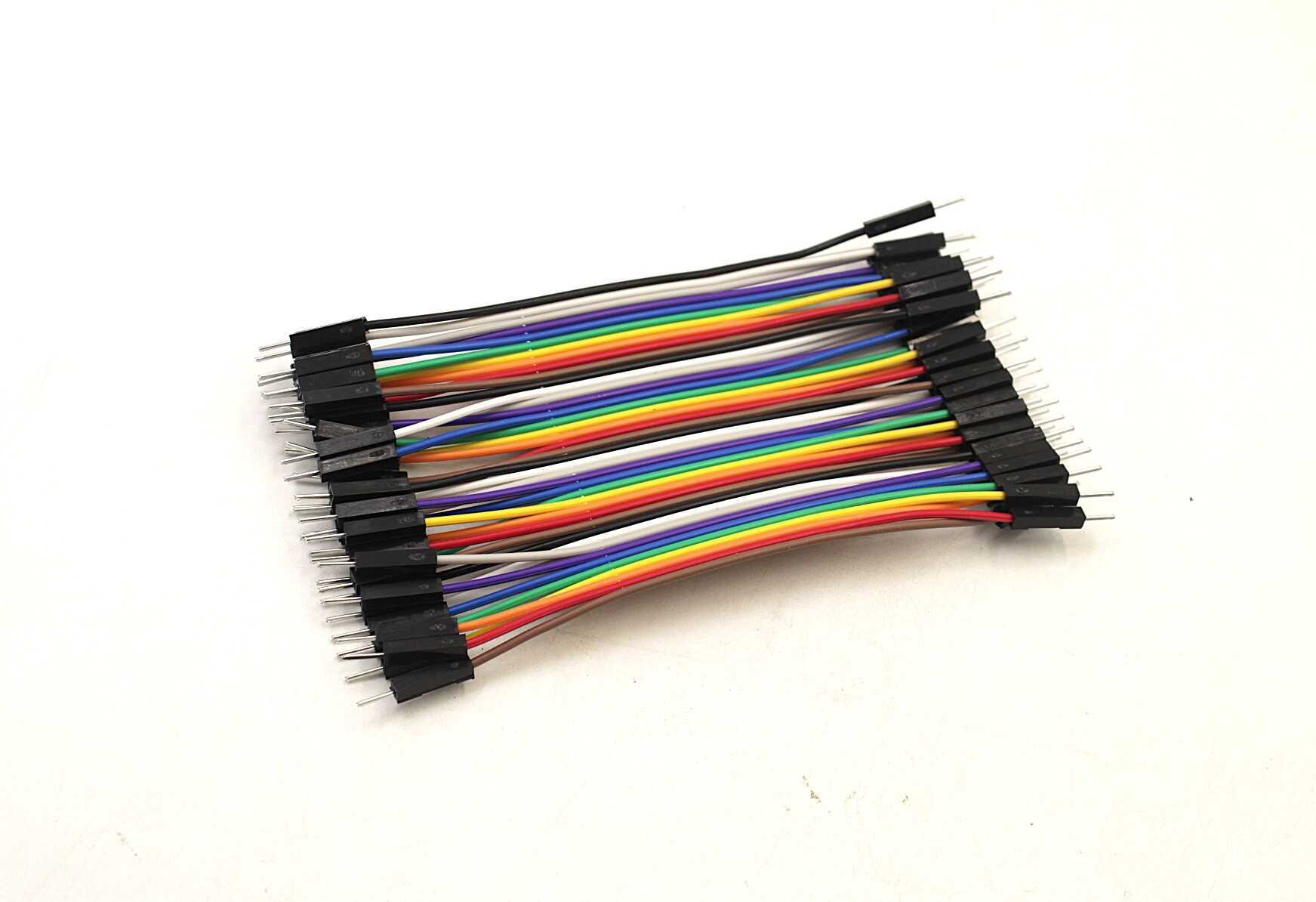
10CM Male To Male Breadboard Jumper Wires 2.54MM – 40Pcs
Colour-coded male-to-male jumper wires for clean breadboard connections. Essential for wiring your 74HC4051 circuit without solder.

0.1/100nF – TH-Multilayer Ceramic Capacitor (Pack of 50)
100nF decoupling capacitors are essential bypass caps for CMOS ICs like the 74HC4051. Pack of 50 so you’ll have plenty for all your projects.
Arduino Code and Control Logic
The Arduino code to read 8 analog channels through the 74HC4051 is clean and simple. The key is mapping the channel number to the correct 3-bit binary select code and writing it to the S0/S1/S2 pins.
// 74HC4051 Multiplexer - Read 8 Analog Channels
// Zbotic.in Tutorial

const int S0 = 4;   // Select bit 0
const int S1 = 3;   // Select bit 1
const int S2 = 2;   // Select bit 2
const int Z  = A0;  // Common signal pin

void setup() {
  pinMode(S0, OUTPUT);
  pinMode(S1, OUTPUT);
  pinMode(S2, OUTPUT);
  Serial.begin(9600);
  Serial.println("74HC4051 Multiplexer Demo");
}

void selectChannel(int channel) {
  // Write 3-bit binary address to select pins
  digitalWrite(S0, (channel >> 0) & 1);
  digitalWrite(S1, (channel >> 1) & 1);
  digitalWrite(S2, (channel >> 2) & 1);
}

void loop() {
  for (int ch = 0; ch < 8; ch++) {
    selectChannel(ch);
    delayMicroseconds(10);  // Settle time for analog signals
    int value = analogRead(Z);
    Serial.print("Channel ");
    Serial.print(ch);
    Serial.print(": ");
    Serial.println(value);
  }
  Serial.println("--- Next scan ---");
  delay(1000);
}
The delayMicroseconds(10) after channel selection is critical for analog applications. The 74HC4051’s on-resistance (~70Ω) combined with the Arduino’s ADC input capacitance (~14pF) creates an RC time constant. Without a small settling delay, you may read the previous channel’s value instead of the current one — a subtle bug that wastes hours of debugging time.
For digital signals, you can skip the settling delay and simply use digitalRead(Z) instead of analogRead(Z).
Using 74HC4051 as a Demultiplexer
Because the 74HC4051 is bidirectional, using it as a demultiplexer requires no hardware change — just swap which side is input and which is output in your code. Connect your single signal to the Z pin and the 8 output channels to your loads (LEDs, relays, etc.).
// 74HC4051 as Demultiplexer - Sequential LED Chaser

const int S0 = 4;
const int S1 = 3;
const int S2 = 2;
const int Z  = 7;  // Signal output pin (digital)

void setup() {
  pinMode(S0, OUTPUT);
  pinMode(S1, OUTPUT);
  pinMode(S2, OUTPUT);
  pinMode(Z, OUTPUT);
}

void selectChannel(int channel) {
  digitalWrite(S0, (channel >> 0) & 1);
  digitalWrite(S1, (channel >> 1) & 1);
  digitalWrite(S2, (channel >> 2) & 1);
}

void loop() {
  for (int ch = 0; ch < 8; ch++) {
    selectChannel(ch);
    digitalWrite(Z, HIGH);  // Send HIGH to selected channel
    delay(200);
    digitalWrite(Z, LOW);   // Turn off before switching
  }
}
Important limitation: The 74HC4051 can only activate one channel at a time. For driving multiple outputs simultaneously, cascade two ICs or use a dedicated output expander like the 74HC595 shift register.

0 Ohm 0.25W Carbon Film Resistor (Pack of 100)
Zero-ohm jumper resistors for clean PCB routing. Great for bridging connections on prototype boards when building your multiplexer circuits.
Practical Project Ideas
Once you’ve mastered the basics, the 74HC4051 opens up a world of possibilities for Indian maker projects:
1. 8-Channel Soil Moisture Monitor
Read 8 capacitive soil moisture sensors across a home garden using just 3 Arduino pins. Display the readings on an OLED or send them to a Blynk dashboard via ESP8266. Total cost: under ₹500 for the complete system.
2. Multi-Zone Temperature Logger
Multiplex 8 NTC thermistors or LM35 temperature sensors to build a room-by-room temperature logger. Log data to an SD card every 5 minutes for energy audit purposes — a practical project for engineering students.
3. Analog Joystick Expansion
A standard PS2-style joystick uses 2 analog pins. With a 74HC4051, you can read 4 joysticks using just 4 pins total (3 select + 1 analog), perfect for building multi-controller game projects on a budget.
4. Cascaded 64-Channel MUX
Connect two 74HC4051s together: use one MUX’s output to feed the Z pin of another, and control the outer IC’s enable pin with the fourth select line from a 74HC138 decoder. This gives you 64 channels with just 6 GPIO pins.
5. Audio Signal Router
The 74HC4051 handles analog audio signals cleanly. Use it to route audio from 8 different sources to a single amplifier, switching between sources with a rotary encoder. Ideal for a DIY audio mixer project.

LM35 Temperature Sensors
Precision analog temperature sensors, perfect for multi-zone temperature monitoring projects using the 74HC4051 multiplexer. Output 10mV/°C, directly readable by Arduino ADC.
Troubleshooting Common Issues
Problem: All channels read the same value
Check that INH pin (Pin 6) is connected to GND, not VCC. If INH is HIGH, the IC is disabled and all channels are disconnected from Z.
Problem: Analog readings are unstable or noisy
Increase the settling delay in your code from 10µs to 50µs or more. Also add a 100nF capacitor between VCC and GND right at the IC pins. Long jumper wires act as antennas — keep them short on the signal lines.
Problem: Channel reads the wrong sensor
Verify your S0/S1/S2 bit order. S0 is the LSB (least significant bit). Double-check the physical channel numbering — Y0–Y7 are not in sequential order on the DIP package (check the datasheet pinout).
Problem: IC gets warm or outputs are all LOW
You may have a short on one of the channel pins, or you’re trying to drive a load directly from the channel pins. The 74HC4051 is not a power driver — its output can only source/sink a few milliamps. Use a transistor or MOSFET for relay/motor loads.
Problem: Works on breadboard but not on PCB
Add decoupling capacitors (100nF ceramic + 10µF electrolytic) on the PCB. Long PCB traces can pick up interference. Also ensure VEE is connected to GND on the PCB — it’s easy to miss this pin.
Frequently Asked Questions
Q: Can I use 74HC4051 with a 3.3V microcontroller like ESP32 or Raspberry Pi?
Yes! The 74HC4051 works from 2V to 6V. Powering it from 3.3V gives full compatibility with ESP32, STM32, and Raspberry Pi GPIO levels. The on-resistance increases slightly (~130Ω at 2V), but it’s perfectly fine for most sensor applications.
Q: What’s the difference between 74HC4051 (8-ch), 74HC4052 (dual 4-ch), and 74HC4053 (triple 2-ch)?
All three are analog switches from the same family. 74HC4052 contains two independent 4-channel MUXs (useful for stereo audio routing), while 74HC4053 has three independent 2-channel switches. Choose based on your channel grouping needs — 4051 is the most versatile for general-purpose use.
Q: Can the 74HC4051 handle AC signals?
Yes, within limits. The 74HC4051 can switch AC signals as long as the signal amplitude stays within VEE to VCC. For audio frequency AC (20Hz–20kHz), it works well. For RF signals, you need dedicated RF switches — the 74HC4051’s switching speed and capacitance make it unsuitable above a few MHz.
Q: How many 74HC4051 ICs can I cascade for more channels?
You can cascade multiple 74HC4051s using their INH (enable) pins. Connect all Z pins together, then use a 3-to-8 decoder (like 74HC138) to enable only one IC at a time. Two ICs = 16 channels, four ICs = 32 channels, all controlled with 6 GPIO pins (3 shared select + 3 enable decoder pins).
Q: Is 74HC4051 available in SMD package?
Yes, the 74HC4051 comes in TSSOP-16, SO-16, and QFN packages for SMD. For breadboard prototyping, use the DIP-16 package. Once your design is finalized, switch to TSSOP-16 for a compact PCB footprint.
Ready to start your multiplexer project? Explore our full range of logic ICs, breadboards, jumper wires, and sensors at Zbotic Electronics Basics. We ship across India with fast delivery — perfect for your next weekend maker project!


Add comment