
pH measurement is one of the most critical analytical parameters in agriculture, aquaculture, hydroponics, water treatment, food processing, and chemical manufacturing. A single pH unit error can mean the difference between healthy plant growth and crop failure, between safe drinking water and health hazards, or between a successful chemical reaction and a failed batch. Yet pH sensor calibration is the step most DIY makers and even many laboratory technicians get wrong — leading to systematic errors that can be 0.5–2 pH units off the true value.
This comprehensive tutorial explains the electrochemistry of pH measurement, why calibration is essential and how often to do it, the step-by-step procedure for both two-point and three-point buffer calibration, how to implement calibration in Arduino firmware, and how to maintain your pH electrode for long service life. Whether you are building a hydroponics pH controller, an aquarium monitor, or an industrial effluent sensor, this guide gives you everything you need for accurate, reliable pH measurement.
1. pH Basics: What It Measures and Why It Matters
pH is the negative base-10 logarithm of the hydrogen ion (H⁺) activity in a solution: pH = -log₁₀[H⁺]. The scale runs from 0 (strongly acidic) to 14 (strongly basic/alkaline), with 7 being neutral at 25°C.
The logarithmic scale means each pH unit represents a 10× change in hydrogen ion concentration. A solution at pH 5 is 10 times more acidic than pH 6 and 100 times more acidic than pH 7. This is why even a 0.3 pH unit measurement error can be significant in biological systems — plant root nutrient uptake, for example, is heavily dependent on precise pH around 5.5–6.5.
Reference values for common Indian applications:
- Drinking water: 6.5–8.5 (BIS IS 10500)
- Hydroponics: 5.5–6.5 (optimal for most crops)
- Aquaponics / aquarium (freshwater): 6.5–7.5
- Swimming pool: 7.2–7.8
- Industrial effluent discharge (CPCB): 5.5–9.0
- Agricultural irrigation water: 6.0–7.0
2. Glass Electrode Theory: The Nernst Equation
Modern pH electrodes use a glass membrane electrode — a thin layer of special glass that is selectively permeable to hydrogen ions. When this membrane contacts the sample solution, a potential difference develops across it proportional to the H⁺ concentration difference between the sample and an internal reference solution inside the electrode.
This potential follows the Nernst equation:
E = E₀ + (RT/nF) × ln(aH)
Where:
- E = measured electrode potential (millivolts)
- E₀ = electrode constant (the isopotential point, where pH = 7 = 0 mV for most electrodes)
- R = gas constant (8.314 J/mol·K)
- T = absolute temperature (Kelvin)
- F = Faraday constant (96485 C/mol)
- n = ionic charge (+1 for H⁺)
At 25°C (298.15 K), the theoretical Nernst slope is -59.16 mV/pH unit. This means: for every 1 unit increase in pH, the electrode voltage changes by -59.16 mV. At pH 4, a fresh electrode outputs about +177 mV; at pH 7 it outputs ~0 mV; at pH 10 it outputs about -177 mV.
A new, well-conditioned electrode achieves close to 100% of this theoretical slope. An old or fouled electrode might only achieve 85–95% — which is why calibration (measuring the actual slope and offset) is necessary.
3. Why pH Electrodes Drift and Why Calibration Is Essential
pH electrodes are not static devices. Their response drifts over time due to several mechanisms:
Glass Membrane Aging
The hydrated gel layer on the glass membrane (which facilitates H⁺ exchange) changes over time. Newly conditioned electrodes may drift 0.1–0.3 pH units per day until stabilised. Old electrodes (6+ months) show reduced sensitivity and slower response time.
Reference Junction Clogging
The reference junction (the small porous ceramic plug at the bottom of the electrode body) can clog with sample particulates, oils, or precipitates. This causes a junction potential that offsets the reading.
Temperature Effects
The Nernst slope is directly proportional to absolute temperature. At 25°C the slope is 59.16 mV/pH; at 35°C it is 61.5 mV/pH; at 15°C it is 56.8 mV/pH. Without temperature compensation, a 10°C ambient change causes approximately 0.3 pH unit systematic error across the pH scale.
Protein Coating / Fouling
In food, beverage, or biological sample applications, proteins coat the glass membrane and change its response. Regular cleaning with enzyme cleaner or 0.1 M HCl restores performance.
Calibration frequency rule of thumb: Calibrate before every measurement session if accuracy is critical. For continuous monitoring installations, calibrate at minimum once per week or any time the electrode is removed from solution.
4. pH Buffer Solutions: What They Are and How to Choose
A pH buffer solution is a mixture of a weak acid and its conjugate base (or a weak base and its conjugate acid) that resists pH changes when small amounts of acid or base are added. Standard buffer solutions have precisely known pH values at known temperatures.
Standard Buffer pH Values at 25°C
| Buffer System | pH at 25°C | Colour (NIST) | Typical Use |
|---|---|---|---|
| Oxalate | 1.68 | — | Strong acid range |
| Citrate / Phthalate | 4.01 | Red/Orange | Acid range calibration |
| Phosphate (neutral) | 6.86 or 7.00 | Yellow/Green | Universal middle point |
| Borate (Borax) | 9.18 or 10.01 | Blue | Basic range calibration |
| Carbonate | 12.45 | — | Strong base range |
Which buffers to use: Choose buffer pH values that bracket your expected measurement range. For hydroponics (5.5–6.5), use pH 4.01 and pH 6.86. For aquarium (6.5–7.5), use pH 6.86 and pH 9.18. For drinking water (6.5–8.5), use pH 6.86 and pH 9.18.
Buying Buffers in India
pH buffer sachets (4.01, 6.86/7.00, 9.18/10.01) are available from Merck, Hanna Instruments, and Milwaukee Instruments dealers across India. They typically cost ₹100–300 per packet of 20 sachets. Each sachet makes 250 mL of buffer solution. Store unused sachets away from heat and light; use opened solution within 3 months.
5. Two-Point Calibration: Step-by-Step Procedure
Two-point calibration is the standard method for most applications. It determines both the electrode’s offset (zero-point shift from ideal pH 7 = 0 mV) and its slope (sensitivity, expressed as mV/pH unit or as a percentage of theoretical).
Equipment Needed
- pH electrode (glass combination electrode)
- pH amplifier/transmitter module (e.g. DFRobot SEN0161 or analog pH kit)
- Two buffer solutions bracketing your measurement range
- Deionised or distilled water for rinsing
- Lint-free tissue or soft cloth for blotting (NOT rubbing)
- Temperature measurement (thermometer or temperature sensor)
- Small beakers or cups for buffer solutions
Step-by-Step Calibration Procedure
- Prepare your workspace: Ensure all containers and the electrode are at the same temperature (ideally 25°C). Temperature variation between electrode and buffer is the most common calibration error.
- Condition the electrode: If the electrode has been in storage solution, rinse it thoroughly with deionised water. Blot gently with lint-free tissue — never rub, as this creates static charge on the glass membrane that takes minutes to dissipate.
- Select your first buffer (middle point, pH 6.86 or 7.00): Pour enough buffer into a clean beaker to cover the electrode’s sensitive tip and reference junction (typically 50 mL is sufficient). Never pour calibration buffer back into the stock bottle — contamination will ruin the rest.
- Immerse the electrode and wait for stabilisation: Watch the mV reading on your meter or Arduino serial monitor. The reading must be stable (±0.5 mV variation for 30 seconds) before recording. Typical stabilisation time: 30–120 seconds for a fresh electrode, 2–5 minutes for an old one.
- Record the mV reading at buffer pH 7: Theoretical value is 0.0 mV at exactly pH 7. The actual value (your offset, E₀) may be -30 to +30 mV for a good electrode. Store this as your calibration offset.
- Rinse the electrode: Remove from the buffer, rinse thoroughly with deionised water, blot gently, and wait 15–30 seconds for equilibration.
- Immerse in second buffer (pH 4.01 or pH 9.18): Repeat the stabilisation wait. Record the mV reading.
-
Calculate slope:
Slope (mV/pH) = (mV_pH4 - mV_pH7) / (pH4 - pH7)
             = (mV_pH4 - mV_pH7) / (4.01 - 7.00)
Slope % = (measured slope / theoretical slope) × 100
Theoretical slope at 25°C = -59.16 mV/pH unit
A healthy electrode shows 95–102% slope. 85–95% is acceptable. Below 85% — clean or replace the electrode.
- Store calibration values in EEPROM (see code section below) so they persist across power cycles.
6. Three-Point Calibration: When and How
Two-point calibration assumes the electrode’s response is perfectly linear across the entire pH range. In reality, glass electrodes show slight non-linearity at extreme pH values (below 2 or above 12), and combination electrodes can have non-linear junction potential contributions. Three-point calibration adds a third buffer measurement to account for this non-linearity.
When to Use Three-Point Calibration
- Measuring samples expected to span a wide pH range (e.g. 3–11)
- Measuring at pH extremes (< 4 or > 10)
- Laboratory-grade accuracy requirements (±0.02 pH)
- Using older or partially degraded electrodes where non-linearity is more pronounced
Three-Point Procedure
- Follow the same procedure as two-point calibration but use three buffers: typically pH 4.01, pH 6.86/7.00, and pH 9.18/10.01
- Measure millivolt readings in all three buffers (always rinse between each)
- Fit a second-order polynomial through the three calibration points
- Use the polynomial equation to convert future mV readings to pH
Three-Point Calibration Math
Given three calibration points (pH₁, mV₁), (pH₂, mV₂), (pH₃, mV₃), solve for coefficients a, b, c in:
pH = a×mV² + b×mV + c
Use Lagrange interpolation or a three-point least-squares fit. In Arduino firmware, you can solve this using a 3×3 linear system or by simply pre-computing the polynomial coefficients offline and hard-coding them.
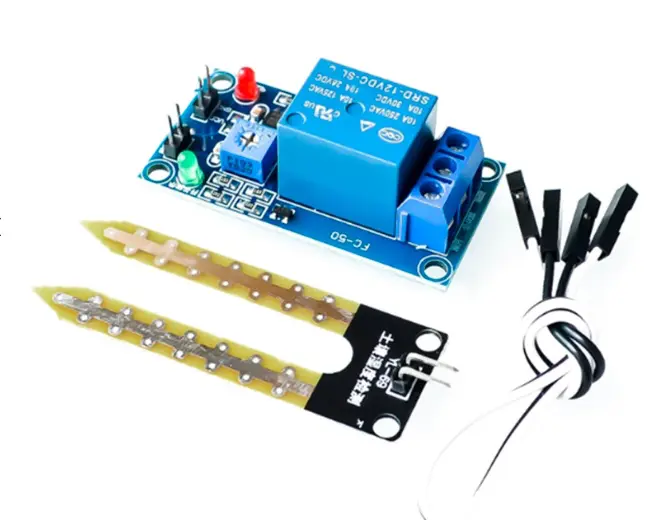
5V 12V Soil Moisture Sensor Relay Control Module
Complete your soil and water quality monitoring system — combine pH measurement with soil moisture sensing for a comprehensive smart agriculture solution with automated relay control.
7. Wiring a pH Module to Arduino / ESP32
Most pH sensor modules for the maker market (DFRobot, Gravity, generic analog pH boards) output an analogue voltage from 0–3.3 V or 0–5 V proportional to pH 0–14. The typical output at pH 7 is approximately VCC/2 (2.5 V for 5 V supply), with higher voltage for lower pH and lower voltage for higher pH.
| pH Module Pin | Arduino Uno | ESP32 |
|---|---|---|
| VCC | 5 V | 3.3 V (or 5V if module accepts) |
| GND | GND | GND |
| PO (Analogue Out) | A0 | GPIO34 (ADC1) |
| DO (Digital Out) | D7 (optional) | GPIO26 (optional) |
Shielding is critical for pH sensors. The glass electrode produces millivolt signals that are extremely sensitive to electrical interference. Connect the electrode shield/drain wire to the circuit’s analogue ground. Run the BNC or DIN-connector cable away from digital signals, motors, and power wires. On ESP32, use a 100 nF capacitor on the ADC pin to filter high-frequency noise.
8. Arduino Code with Calibration Implementation
// pH Sensor with Two-Point Calibration
// Zbotic.in

#include <EEPROM.h>

#define PH_PIN        A0
#define SAMPLES       10      // Samples to average
#define VREF          5.0     // Arduino ADC reference voltage
#define ADC_BITS      1023.0  // 10-bit ADC

// EEPROM addresses for calibration storage
#define ADDR_SLOPE    0
#define ADDR_OFFSET   4

// Default calibration (uncalibrated — replace after calibration)
float cal_slope  = -59.16;  // mV/pH (theoretical)
float cal_offset = 2.500;   // Voltage at pH 7.00 (V)

void setup() {
  Serial.begin(9600);
  loadCalibration();
  Serial.println("pH Sensor Ready. Send 'C' to calibrate.");
}

void loop() {
  if (Serial.available() && Serial.read() == 'C') {
    runCalibration();
  }

  float voltage = readVoltage();
  float ph = voltageToPH(voltage);

  Serial.print("V: "); Serial.print(voltage, 3);
  Serial.print("V | pH: "); Serial.println(ph, 2);

  delay(1000);
}

float readVoltage() {
  long sum = 0;
  for (int i = 0; i < SAMPLES; i++) {
    sum += analogRead(PH_PIN);
    delay(10);
  }
  return (sum / (float)SAMPLES) * (VREF / ADC_BITS);
}

float voltageToPH(float voltage) {
  // Convert voltage to mV delta from midpoint
  float mV = (voltage - cal_offset) * 1000.0;
  // pH = 7.0 - (mV / slope)
  return 7.0 - (mV / cal_slope);
}

void runCalibration() {
  Serial.println("n=== TWO-POINT CALIBRATION ===");

  // Point 1: pH 6.86 buffer
  Serial.println("Step 1: Place electrode in pH 6.86 buffer.");
  Serial.println("Wait for stable reading, then send 'Y'.");
  while (!Serial.available()) { delay(100); }
  Serial.read();
  float v_buf1 = readVoltage();
  Serial.print("Recorded V_pH6.86 = "); Serial.println(v_buf1, 4);

  // Point 2: pH 4.01 buffer
  Serial.println("nStep 2: Rinse, then place in pH 4.01 buffer.");
  Serial.println("Wait for stable reading, then send 'Y'.");
  while (!Serial.available()) { delay(100); }
  Serial.read();
  float v_buf2 = readVoltage();
  Serial.print("Recorded V_pH4.01 = "); Serial.println(v_buf2, 4);

  // Calculate calibration parameters
  // Two points: (pH=6.86, V=v_buf1), (pH=4.01, V=v_buf2)
  float pH1 = 6.86, pH2 = 4.01;
  cal_slope  = (v_buf2 - v_buf1) / (pH2 - pH1) * 1000.0; // mV/pH
  cal_offset = v_buf1; // Voltage at pH 6.86 (close to 7.00)

  // Adjust offset to be relative to pH 7.00
  cal_offset = v_buf1 + (cal_slope / 1000.0) * (pH1 - 7.0);

  float slopePct = (cal_slope / -59.16) * 100.0;
  Serial.print("nCalibrated slope: "); Serial.print(cal_slope, 2);
  Serial.print(" mV/pH ("); Serial.print(slopePct, 1); Serial.println("% of theoretical)");
  Serial.print("Offset V at pH7: "); Serial.println(cal_offset, 4);

  if (slopePct < 85.0) {
    Serial.println("WARNING: Slope < 85%. Clean or replace electrode.");
  }

  saveCalibration();
  Serial.println("Calibration saved to EEPROM.");
}

void saveCalibration() {
  EEPROM.put(ADDR_SLOPE, cal_slope);
  EEPROM.put(ADDR_OFFSET, cal_offset);
}

void loadCalibration() {
  float s, o;
  EEPROM.get(ADDR_SLOPE, s);
  EEPROM.get(ADDR_OFFSET, o);
  // Sanity check — valid slope is -45 to -65 mV/pH
  if (s > -45.0 && s < -65.0) {
    cal_slope = s;
    cal_offset = o;
    Serial.println("Loaded calibration from EEPROM.");
  }
}
Temperature Compensation (Optional but Recommended)
// Add temperature compensation using DS18B20 or NTC thermistor
// Theoretical Nernst slope at temperature T (Kelvin):
float slopeAtTemperature(float tempC) {
  float T = tempC + 273.15;
  return -(8.314 * T) / (1 * 96485) * log(10) * 1000; // mV/pH
}
// Use this dynamic slope in voltageToPH() instead of fixed cal_slope
BMP280 Barometric Pressure and Altitude Sensor
Add pressure and temperature measurement to your water quality monitoring station — the BMP280 provides accurate ambient temperature for pH temperature compensation via I2C.
9. pH Electrode Maintenance and Storage
Routine Cleaning
- After every use: Rinse with deionised water and blot gently with lint-free tissue.
- Weekly (continuous use): Soak in pH 4.01 buffer for 10 minutes to recondition the glass membrane and clean the reference junction.
- Monthly or when fouled: Soak in 0.1 M HCl for 30 minutes (removes protein and mineral deposits), then rinse thoroughly with deionised water and re-calibrate.
- Oily or greasy samples: Wipe gently with isopropyl alcohol on a lint-free tissue, then rinse with deionised water.
Storage
- Short term (days to weeks): Store in pH 4.01 buffer or 3 M KCl electrode storage solution. Never store dry — a dried glass membrane can crack and become permanently damaged.
- Long term (months): Fill the storage cap with storage solution and seal. Check every 2–4 weeks and top up if needed.
- Never store in: Deionised water (causes leaching), distilled water, or pH 7 buffer (promotes bacterial growth in buffer).
Signs Your Electrode Needs Replacement
- Calibration slope below 80% even after cleaning
- Response time exceeds 5 minutes in buffer
- Readings oscillate and never stabilise
- Visible cracks or chips in the glass tip
- Gel or air bubble visible inside the glass tip through the membrane
10. Troubleshooting Inaccurate pH Readings
Reading is Consistently Off by Same Amount (Offset Error)
The electrode’s E₀ (zero point) has shifted. Recalibrate with pH 7 buffer first. If the mV reading in pH 7 buffer is more than ±50 mV from 0 mV, the electrode may need cleaning. Soak in pH 4 buffer for 30 minutes and retry.
Reading is Off More at Extremes Than Near pH 7 (Slope Error)
The electrode’s Seebeck coefficient has degraded. Calculate the slope percentage during calibration. Below 90% — deep clean the electrode. Below 85% — consider replacement. Check that extension cable is not too long or poorly shielded.
Reading Fluctuates Widely (Noisy Signal)
Check electrical isolation — the pH circuit must be isolated from grounds connected to motors, relays, or switching supplies. Add a 100 nF filter capacitor to the ADC input. Ensure the cable shield is connected to analogue GND only (not digital GND or power GND). In severe EMI environments, use a BNC connector and coaxial cable instead of unshielded wires.
Reading Drifts Slowly Over Hours
Temperature drift is the most common cause. Implement temperature compensation using a co-located temperature sensor. Also check that the electrode’s reference junction is not slowly clogging — immerse in pH 7 buffer and observe if the reading stabilises within 2 minutes.
Frequently Asked Questions
Q: How often should I recalibrate my pH sensor for a hydroponics system?
For hydroponics, calibrate at minimum once per week. If the nutrient solution temperature fluctuates significantly (common in greenhouses without climate control), calibrate every 3–4 days. Always calibrate after cleaning the electrode or after any period of dry storage. Use pH 4.01 and 6.86 buffers for the typical 5.5–6.5 hydroponics range.
Q: Can I make my own pH buffer solutions at home?
Yes, but it requires analytical-grade chemicals and precise weighing. Common home buffers: 0.05 M potassium hydrogen phthalate (pH 4.01), or a phosphate mixture (pH 6.86/7.00). However, for calibration purposes, commercially prepared NIST-traceable buffer sachets are strongly recommended — they are inexpensive, accurate, and eliminate preparation errors.
Q: What is the difference between ATC (Automatic Temperature Compensation) and manual temperature compensation?
ATC uses a thermistor built into the electrode or a separate temperature sensor to automatically adjust the pH calculation for the Nernst slope change with temperature. Manual TC requires the user to set the sample temperature on the meter or enter it into the firmware. For Arduino projects, implement ATC by reading a co-located temperature sensor (DS18B20 or DHT20) and using the temperature-adjusted slope in the voltage-to-pH formula.
Q: How do I know if my pH calibration was successful?
After completing a two-point calibration, validate by placing the electrode in a third buffer of a different pH value and checking the reading against the known buffer pH. A good calibration should show ±0.1 pH accuracy in the validation buffer. If the error is greater than ±0.2 pH, repeat the calibration procedure more carefully, paying attention to electrode equilibration time and temperature matching.
Q: Can I use a pH module with ESP32 and upload data to the cloud?
Yes. Connect the pH module’s analogue output to an ESP32 ADC1 pin (GPIO32–39), implement the calibration in firmware, and use MQTT or HTTP to publish readings to cloud platforms like ThingSpeak, Blynk, or AWS IoT. For India-based deployments, ensure the ESP32 is powered from a stable regulated supply — the ESP32’s ADC is very sensitive to VCC variation, and an unstable power supply will cause noisy pH readings. Use the ESP32’s built-in ADC calibration via esp_adc_cal library for best accuracy.
Conclusion
Accurate pH measurement is not just about having a good sensor — it is fundamentally about proper calibration, maintenance, and understanding the physical principles behind the measurement. A two-point calibration with quality NIST-traceable buffer solutions is sufficient for most applications and takes less than 5 minutes to perform once you have the procedure memorised. For wide-range or high-precision applications, invest the extra time in three-point calibration.
The Arduino code and calibration formulas in this tutorial give you everything needed to implement a complete, calibrated pH monitoring system. Add temperature compensation with a DS18B20 or DHT20, store calibration coefficients in EEPROM, and add IoT connectivity via Wi-Fi or GSM for a professional-grade water quality monitoring solution at a fraction of the cost of commercial instruments.
Remember: the electrode is a consumable. Even a perfectly implemented firmware system cannot compensate for a degraded electrode. Monitor your calibration slope percentage at every calibration session and replace the electrode when it drops below 85% — this is the single most important maintenance action for long-term pH measurement accuracy.
Build Your Water Quality Monitoring System
Find sensors, Arduino boards, ESP32 modules, and all components for your pH and water quality monitoring project at Zbotic — India’s electronics store for makers and engineers.


Add comment